US6147932A - Acoustic transducer - Google Patents
Acoustic transducer Download PDFInfo
- Publication number
- US6147932A US6147932A US09/307,266 US30726699A US6147932A US 6147932 A US6147932 A US 6147932A US 30726699 A US30726699 A US 30726699A US 6147932 A US6147932 A US 6147932A
- Authority
- US
- United States
- Prior art keywords
- mandrel
- anvil
- acoustic transducer
- active acoustic
- region
- Prior art date
- Legal status (The legal status is an assumption and is not a legal conclusion. Google has not performed a legal analysis and makes no representation as to the accuracy of the status listed.)
- Expired - Lifetime
Links
- 229910000831 Steel Inorganic materials 0.000 claims description 5
- 239000010959 steel Substances 0.000 claims description 5
- 239000000463 material Substances 0.000 claims description 3
- 238000007789 sealing Methods 0.000 claims 3
- 238000000034 method Methods 0.000 description 11
- 239000000919 ceramic Substances 0.000 description 9
- 238000004891 communication Methods 0.000 description 5
- 230000006835 compression Effects 0.000 description 5
- 238000007906 compression Methods 0.000 description 5
- 230000004888 barrier function Effects 0.000 description 3
- 238000004519 manufacturing process Methods 0.000 description 3
- 238000001816 cooling Methods 0.000 description 2
- 238000013461 design Methods 0.000 description 2
- 238000010438 heat treatment Methods 0.000 description 2
- 238000003754 machining Methods 0.000 description 2
- 238000012986 modification Methods 0.000 description 2
- 230000004048 modification Effects 0.000 description 2
- 238000013459 approach Methods 0.000 description 1
- 230000007423 decrease Effects 0.000 description 1
- 238000011161 development Methods 0.000 description 1
- 230000018109 developmental process Effects 0.000 description 1
- 238000005553 drilling Methods 0.000 description 1
- 230000000694 effects Effects 0.000 description 1
- 238000005516 engineering process Methods 0.000 description 1
- 238000011065 in-situ storage Methods 0.000 description 1
- 238000005259 measurement Methods 0.000 description 1
- 239000003129 oil well Substances 0.000 description 1
- 230000008569 process Effects 0.000 description 1
- 230000001681 protective effect Effects 0.000 description 1
- 230000000717 retained effect Effects 0.000 description 1
- 238000012546 transfer Methods 0.000 description 1
- 230000003313 weakening effect Effects 0.000 description 1
Images
Classifications
-
- B—PERFORMING OPERATIONS; TRANSPORTING
- B06—GENERATING OR TRANSMITTING MECHANICAL VIBRATIONS IN GENERAL
- B06B—METHODS OR APPARATUS FOR GENERATING OR TRANSMITTING MECHANICAL VIBRATIONS OF INFRASONIC, SONIC, OR ULTRASONIC FREQUENCY, e.g. FOR PERFORMING MECHANICAL WORK IN GENERAL
- B06B1/00—Methods or apparatus for generating mechanical vibrations of infrasonic, sonic, or ultrasonic frequency
- B06B1/02—Methods or apparatus for generating mechanical vibrations of infrasonic, sonic, or ultrasonic frequency making use of electrical energy
- B06B1/06—Methods or apparatus for generating mechanical vibrations of infrasonic, sonic, or ultrasonic frequency making use of electrical energy operating with piezoelectric effect or with electrostriction
- B06B1/0607—Methods or apparatus for generating mechanical vibrations of infrasonic, sonic, or ultrasonic frequency making use of electrical energy operating with piezoelectric effect or with electrostriction using multiple elements
- B06B1/0611—Methods or apparatus for generating mechanical vibrations of infrasonic, sonic, or ultrasonic frequency making use of electrical energy operating with piezoelectric effect or with electrostriction using multiple elements in a pile
Definitions
- This invention relates to the field of acoustic transducers that use piezoelectric elements installed on a mandrel as acoustic signal generators for use in downhole telemetry applications. More particularly, the invention relates to an improved transducer apparatus configuration and method of assembly allowing wider machining tolerances and easier assembly than an earlier version of acoustic transducer patented by the applicant herein.
- the transducer in that patent comprises a hollow unitary mandrel having a cylindrical recess formed in the outer wall of the mandrel within which recess is captured a stack of piezoelectric elements in a temperature compensated interference fit.
- the transducer assembly also includes a power source and a protective shell that covers the region of the mandrel and captures the piezoelectric elements.
- the mandrel can be adapted to connect to production tubing that serves as the waveguide between the transducer downhole and the surface.
- the transducer is further adapted to receive information from a downhole measurement device such as a pressure/temperature gage.
- Acoustic transducers tools such as the one disclosed in the '836 patent, employ stressed piezoelectric elements. Compression of the piezoelectric elements is desirable to protect the ceramics from tensile failure.
- a stack of washer-shaped piezoelectric discs is positioned about a cylindrical recess formed in a hollow mandrel. The discs are securely retained by thermal-expansion compensating rings which are, in turn, secured by the edge of the recess into which the discs and compensating rings are positioned.
- the necessary compressive stress is obtained as a consequence of the method of assembly described there.
- the piezoelectric discs and thermal-expansion compensating rings are provided as pairs of half-cylinders that are emplaced in the cylindrical recess of the mandrel.
- the positioning of the half-cylinders takes place after the mandrel has been heated to sufficient temperature so as to cause the mandrel (and consequently the cylindrical recess cut into the mandrel) to expand slightly.
- the halves of the transducer elements and temperature compensating rings are positioned in the expanded recess, and the mandrel is allowed to cool. As the cooling takes place the mandrel contracts and the piezoelectric elements are captured securely in an interference fit in the mandrel recess.
- the present invention provides a simplified acoustic transducer characterized by a one-piece mandrel in the form of a modified cylinder symmetric about a central axis.
- the mandrel has a first mandrel region including an outer surface substantially parallel to the central axis and at a first substantially constant radial distance from the central axis.
- the mandrel also has a second mandrel region including an outer surface substantially parallel to the central axis and at a second substantially constant radial distance from the central axis, the second substantially constant radial distance being less than the first substantially constant radial distance.
- the first region includes a shoulder member extending from the outer surface of the first region to the outer surface of the second region.
- the transducer apparatus further includes an anvil in the form of a cylinder symmetric about the central axis and having first and second ends, an outer anvil surface substantially parallel to the central axis and at a third substantially constant radial distance from the central axis, and a central aperture bound by an inner anvil surface that is substantially parallel to the central axis.
- the inner anvil surface is at a fourth substantially constant radial distance from the central axis, the fourth substantially constant radial distance being less than the third substantially constant radial distance but, in the assembled condition, only slightly greater than the second substantially constant radial distance, resulting in an interference fit between the inner anvil surface and the outer surface of the second mandrel region.
- the anvil also includes a base member in the region of the first end extending from the outer anvil surface to the inner anvil surface. The anvil is positioned so that part of the second region of the mandrel passes through the central aperture bound by the inner surface of the anvil.
- the acoustic transducer apparatus also includes a plurality of washer-shaped discs having an outer radius and an inner radius, the inner radius being slightly larger than the substantially constant radial distance associated with the outer surface of the second region of the mandrel, and the outer radius being larger than the inner radius. The plurality of discs are captured between the shoulder member of the first region of the mandrel and the base of the anvil in a pre-stressed interference fit.
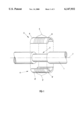
- FIG. 1 is a partially-exploded side view of a the portion of an acoustic transducer mandrel with transducer elements positioned as described in the '836 patent.
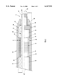
- FIG. 2 is a cross section view of a portion of an acoustic transducer mandrel with transducer elements positioned according to an new embodiment different from that described in the '836 patent.
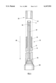
- FIG. 3 is a partial cross-sectional view of one embodiment of an acoustic transducer tool and assembly equipment illustrating an extension method of the assembling tool components.
- the transducer elements are emplaced into a slot in the mandrel as two half cylinders.
- the half cylinders each comprise two portions, which are present for compensation of thermal expansion, and one sandwich-style PZT ceramic assembly (also provided in two portions).
- This PZT ceramic assembly serves as the active transducer element.
- An axial interference fit exists between the half cylinders and the mandrel. This places the mandrel in axial tension while the half cylinders are in axial compression. This pre-stress is critical to the proper operation of the tool. The ceramics must not be put into tension because the PZT is weak in tension.
- FIG. 1 illustrates an example of the type of assembly just described.
- a mandrel 1 is provided which includes a cylindrical recess 2.
- a cylindrical sandwich-style transducer is provided which, when the transducer and the mandrel are at or close to the same temperature, has a length slightly longer than the length of the recess 2.
- the cylindrical sandwich-style transducer comprises two portions, 3 and 4, each of which forms substantially half of the overall transducer unit. Each half includes stacked piezoelectric elements 5 and 5' which, when assembled, surround the mandrel 1 in the region of the cylindrical recess 2.
- Each half portion of the sandwich-style transducer likewise includes two thermal expansion rings (expansion compensators) 6 and 6' located on either end of the stack of piezoelectric elements, 5 and 5', respectively.
- the mandrel 1 is heated so that it expands along its axial dimension 7.
- the cylindrical recess 2 also enlarges slightly.
- the two halves 3 and 4 of the transducer are then emplaced opposite each other in the cylindrical recess 2, and the mandrel 1 is allowed to cool. As it cools, the recess 2 contracts with the result that the piezoelectric elements 5 and 5' are compressed and prestressed. If in a given case the tolerances are especially tight, in addition to heating (expanding) the mandrel, a charge can be exerted on the PZT elements to cause them to shrink slightly to facilitate assembly.
- the function of the tool is to produce stress waves in oilfield tubulars such as drill pipe and production tubing. These stress waves act as carrier waves to transmit information by wireless means in wells that are being drilled or produced, for example. This allows for communication between the surface and below-surface components, such as drill bits and completion equipment. Because of the interference fit, in practice, the lengths of the cylinders and the slot in the mandrel that receives them must be held to close machining tolerances.
- the remainder of this disclosure concerns a different design that preserves the advantages of the earlier '836 patent design, but allows for wider tolerances. It is also easier to assemble, and allows more precise control of the state of prestress.
- the two cylindrical halves of the original transducer elements are replaced by a single complete hollow cylindrical element. This new single element is considerably easier to manufacture than the two half cylinders.
- the slot in the original mandrel is, in this embodiment, formed by two pieces: the mandrel and the separate hollow cylindrical anvil. Specifically, as described in detail below, a machined portion of the mandrel provides one boundary of the slot and the edge of the anvil provides the other boundary. The anvil is placed onto the mandrel as a thermal interference fit. Using this improved assembly, the ceramics (piezoelectric elements) can be placed in a controlled state of compression.
- FIG. 2 illustrates a partially cut-away view of the portion of the apparatus of the present invention that includes the ceramic transducer elements.
- cylindrical elements are described, they generally share a single central axis of symmetry 70, as shown, when in their assembled configuration. It is recognized that in practice, some of the elements may not be precisely aligned along the same axis of symmetry, however, for convenience in this disclosure the single central axis of symmetry 70 is defined and used as a general point of reference.
- the claims are intended to encompass cases where slight deviations relative to the axis of symmetry are present.
- the claimed invention is robust in the respect that it can operate within a range of tolerances.
- a hollow tubular mandrel 10 typically comprised of steel, is provided. (It is recognized that other suitable materials exist and will be apparent to those skilled in the art of drilling operations. Unless otherwise noted, where steel is specified herein, other suitable materials are intended to fall within the description.)
- the mandrel 10 has been machined or otherwise shaped to include a first region of a given thickness A between the inner and outer surfaces, and a second region of a different given thickness B between the inner and outer surfaces. Thickness A is greater than thickness B, and a surface is described delineating the boundary of the first region.
- This surface is generally perpendicular to the central axis of symmetry 70 and for purposes of this description will be referred to as the mandrel shoulder 12 which likewise serves as one boundary of a slot (analogous to that described above) into which a sandwich-style transducer is emplaced.
- the sandwich-style transducer 30 comprising two cylindrical thermal expansion compensators 14, 16 and a stack of washer-shaped piezoelectric elements 15 positioned between the compensators.
- the sandwich-style transducer 30 describes a hollow cylindrical component including both an inner and outer annular surface as well as first and second edges, one on each end of the cylinder.
- the sandwich-style transducer 30 is positioned over the narrower portion of the mandrel 10 so that its first edge is flush against the mandrel shoulder 12.
- the figure also illustrates a hollow cylindrical anvil 20 including, at one of its ends, a threaded region 24 and, at its opposite end, a surface, which is generally perpendicular to the central axis of symmetry 70.
- that surface is referred to as the anvil base 22.
- the anvil 20 is also positioned over the narrower portion of the mandrel 10 so that the anvil base 22 is flush against the second edge of the sandwich-style transducer 30. (Details about how the anvil is positioned, and how an interference fit is accomplished, are provided later in this disclosure.) In this way, the sandwich-style acoustic transducer 30 is captured between the mandrel shoulder 12 and the anvil base 22.
- a cylindrical pressure housing 40 is positioned about the previously described components. It surrounds the entire assembly just described, except that a portion of the narrower part of the mandrel (the second region of the mandrel having thickness B) extends beyond the housing 40 and bears a terminus 11 which, in the preferred embodiment, includes threads 17. Also shown in the figure is an o-ring 26 which is used in the preferred embodiment to form a seal between the housing 40, the anvil 20 and the mandrel 10 in the location shown in the figure where portions of each of those elements are in close proximity. An interference fit 28 exists between the anvil 20 and the mandrel 10 in the final tool thus assembled, and is discussed further below in conjunction with the method of assembly of the tool.
- the dimension C representing the distance between the inner and outer diameter of the cylindrical sandwich-style ceramic transducer 30 and the dimension D representing the distance from the outer surface of the narrower portion of the mandrel 10 and the outer perimeter surface of the housing 40.
- the dimension D representing the distance from the outer surface of the narrower portion of the mandrel 10 and the outer perimeter surface of the housing 40.
- FIG. 3 Assembly of the tool just described is accomplished with the aid of a commercial hydraulic jack.
- the hydraulic jack 100 is connected to the wider end of the mandrel 10 which, as illustrated in the figure, has been modified to include oilfield threads 90 that can be screwed onto the hydraulic jack, as shown.
- oilfield threads 90 that can be screwed onto the hydraulic jack, as shown.
- a push rod 92 is placed in the central opening of the hollow cylindrical mandrel 10, and a removable friction-slip assembly 95 is placed on top of the push rod.
- the friction-slip assembly serves as a barrier against which force can be exerted by the push rod 92.
- Alternative means for creating such a barrier exist and will be apparent to those skilled in the art practicing the invention.
- threads can be included at the terminus 11 of the mandrel 10, and a cap can be screwed on to create a surface against which the push rod 92 will push, in the operation described below.
- the mandrel can include a welded (or otherwise integral) plug in the region of the terminus 11 of the mandrel.
- the mandrel prefferably be manufactured from a single drilled-out billet with an undrilled portion in the region of the terminus 11.
- the portion of the terminus 11 including the barrier or plug can be cut off an discarded.
- the jack 100 is used to temporarily extend the length (stretch) the mandrel 10 by pulling the mandrel in the relative direction shown by the arrow 80 against the resistance provided by the push rod 92.
- the sandwich-style transducer 30 is slid over the narrower part of the mandrel 10 into position against the mandrel shoulder 12. In order to aid in this process, an alignment shoulder can be machined into the mandrel.
- the anvil 20 is heated to a temperature sufficient to allow it, due to thermal expansion, to slide into position so that the anvil base 22 lies adjacent to the sandwich-style transducer 30. It may be necessary for care to be taken, using techniques known to those skilled in the art, to cool or otherwise protect the expansion compensator 16, which will contact the anvil base 22. As the anvil 20 cools to ambient temperature it will shrink to an interference fit with the mandrel 10. After sufficient cooling, the hydraulic jack 100, push rod 92 and friction-slip assembly 95 are released and removed. The mandrel 10 returns substantially to its original dimensions, and, in doing so the ceramics in the sandwich-style transducer 30 are subjected to compression. The final level of compression is controlled by the initial stretch imposed by the hydraulic jack as well as the secondary heating of the expansion compensator by contact with the heated anvil.
Abstract
Description
Claims (17)
Priority Applications (1)
| Application Number | Priority Date | Filing Date | Title |
|---|---|---|---|
| US09/307,266 US6147932A (en) | 1999-05-06 | 1999-05-06 | Acoustic transducer |
Applications Claiming Priority (1)
| Application Number | Priority Date | Filing Date | Title |
|---|---|---|---|
| US09/307,266 US6147932A (en) | 1999-05-06 | 1999-05-06 | Acoustic transducer |
Publications (1)
| Publication Number | Publication Date |
|---|---|
| US6147932A true US6147932A (en) | 2000-11-14 |
Family
ID=23188964
Family Applications (1)
| Application Number | Title | Priority Date | Filing Date |
|---|---|---|---|
| US09/307,266 Expired - Lifetime US6147932A (en) | 1999-05-06 | 1999-05-06 | Acoustic transducer |
Country Status (1)
| Country | Link |
|---|---|
| US (1) | US6147932A (en) |
Cited By (30)
| Publication number | Priority date | Publication date | Assignee | Title |
|---|---|---|---|---|
| US20030142586A1 (en) * | 2002-01-30 | 2003-07-31 | Shah Vimal V. | Smart self-calibrating acoustic telemetry system |
| US20040145970A1 (en) * | 2003-01-28 | 2004-07-29 | Extreme Engineering Ltd. | Apparatus for receiving downhole acoustic signals |
| US20040163822A1 (en) * | 2002-12-06 | 2004-08-26 | Zhiyi Zhang | Combined telemetry system and method |
| US6791470B1 (en) | 2001-06-01 | 2004-09-14 | Sandia Corporation | Reducing injection loss in drill strings |
| US20050001517A1 (en) * | 2003-07-03 | 2005-01-06 | Pathfinder Energy Services, Inc. | Composite backing layer for a downhole acoustic sensor |
| US20050002276A1 (en) * | 2003-07-03 | 2005-01-06 | Pathfinder Energy Services, Inc. | Matching layer assembly for a downhole acoustic sensor |
| US20050000279A1 (en) * | 2003-07-03 | 2005-01-06 | Pathfinder Energy Services, Inc. | Acoustic sensor for downhole measurement tool |
| US20050156754A1 (en) * | 2004-01-20 | 2005-07-21 | Halliburton Energy Services, Inc. | Pipe mounted telemetry receiver |
| US20060187755A1 (en) * | 2005-02-24 | 2006-08-24 | The Charles Stark Draper Laboratory, Inc. | Methods and systems for communicating data through a pipe |
| US20060219438A1 (en) * | 2005-04-05 | 2006-10-05 | Halliburton Energy Services, Inc. | Wireless communications in a drilling operations environment |
| US20070126595A1 (en) * | 2005-10-28 | 2007-06-07 | Murphy Eugene A | Logging system, method of logging an earth formation and method of producing a hydrocarbon fluid |
| US7339494B2 (en) | 2004-07-01 | 2008-03-04 | Halliburton Energy Services, Inc. | Acoustic telemetry transceiver |
| US20090022011A1 (en) * | 2007-07-20 | 2009-01-22 | Precision Energy Services, Inc. | Acoustic transmitter comprising a plurality of piezoelectric plates |
| US7513147B2 (en) | 2003-07-03 | 2009-04-07 | Pathfinder Energy Services, Inc. | Piezocomposite transducer for a downhole measurement tool |
| US20090129203A1 (en) * | 2007-11-20 | 2009-05-21 | Precision Energy Services, Inc. | Monopole acoustic transmitter comprising a plurality of piezoelectric discs |
| US7587936B2 (en) | 2007-02-01 | 2009-09-15 | Smith International Inc. | Apparatus and method for determining drilling fluid acoustic properties |
| US20100020638A1 (en) * | 2008-07-24 | 2010-01-28 | Precision Energy Services, Inc. | Monopole acoustic transmitter ring comprising piezoelectric material |
| EP2157278A1 (en) | 2008-08-22 | 2010-02-24 | Schlumberger Holdings Limited | Wireless telemetry systems for downhole tools |
| EP2157279A1 (en) | 2008-08-22 | 2010-02-24 | Schlumberger Holdings Limited | Transmitter and receiver synchronisation for wireless telemetry systems technical field |
| US20110018735A1 (en) * | 2009-07-27 | 2011-01-27 | Fernando Garcia-Osuna | Acoustic communication apparatus for use with downhole tools |
| US20110073293A1 (en) * | 2009-09-25 | 2011-03-31 | Gauthier Benoit G | Thermal Wick Cooling For Vibroacoustic Transducers |
| US20110176387A1 (en) * | 2008-11-07 | 2011-07-21 | Benoit Froelich | Bi-directional wireless acoustic telemetry methods and systems for communicating data along a pipe |
| CN102205309A (en) * | 2010-11-24 | 2011-10-05 | 浙江师范大学 | Hydraulic pressurizing device for high-power radial compound ultrasonic tube |
| US8117907B2 (en) | 2008-12-19 | 2012-02-21 | Pathfinder Energy Services, Inc. | Caliper logging using circumferentially spaced and/or angled transducer elements |
| WO2012131600A2 (en) | 2011-03-30 | 2012-10-04 | Schlumberger Technology B.V. | Transmitter and receiver synchronization for wireless telemetry systems |
| US8726726B2 (en) | 2009-06-25 | 2014-05-20 | Sinvent As | Sensor unit for a logging tool and a logging tool with at least two sensor elements |
| EP2762673A1 (en) | 2013-01-31 | 2014-08-06 | Service Pétroliers Schlumberger | Mechanical filter for acoustic telemetry repeater |
| EP2763335A1 (en) | 2013-01-31 | 2014-08-06 | Service Pétroliers Schlumberger | Transmitter and receiver band pass selection for wireless telemetry systems |
| WO2017147721A1 (en) * | 2016-03-04 | 2017-09-08 | Xact Downhole Telemetry Inc. | Method and system for controlling voltage applied across a piezoelectric stack of a downhole acoustic transmitter |
| US10557315B2 (en) * | 2013-09-27 | 2020-02-11 | Cold Bore Technology Inc. | Methods and apparatus for operatively mounting actuators to pipe |
Citations (2)
| Publication number | Priority date | Publication date | Assignee | Title |
|---|---|---|---|---|
| US5357486A (en) * | 1992-12-02 | 1994-10-18 | Innovative Transducers Inc. | Acoustic transducer |
| US5703836A (en) * | 1996-03-21 | 1997-12-30 | Sandia Corporation | Acoustic transducer |
-
1999
- 1999-05-06 US US09/307,266 patent/US6147932A/en not_active Expired - Lifetime
Patent Citations (2)
| Publication number | Priority date | Publication date | Assignee | Title |
|---|---|---|---|---|
| US5357486A (en) * | 1992-12-02 | 1994-10-18 | Innovative Transducers Inc. | Acoustic transducer |
| US5703836A (en) * | 1996-03-21 | 1997-12-30 | Sandia Corporation | Acoustic transducer |
Cited By (65)
| Publication number | Priority date | Publication date | Assignee | Title |
|---|---|---|---|---|
| US6791470B1 (en) | 2001-06-01 | 2004-09-14 | Sandia Corporation | Reducing injection loss in drill strings |
| US20030142586A1 (en) * | 2002-01-30 | 2003-07-31 | Shah Vimal V. | Smart self-calibrating acoustic telemetry system |
| US7163065B2 (en) | 2002-12-06 | 2007-01-16 | Shell Oil Company | Combined telemetry system and method |
| US20040163822A1 (en) * | 2002-12-06 | 2004-08-26 | Zhiyi Zhang | Combined telemetry system and method |
| US7565936B2 (en) | 2002-12-06 | 2009-07-28 | Shell Oil Company | Combined telemetry system and method |
| US20070137853A1 (en) * | 2002-12-06 | 2007-06-21 | Zhiyi Zhang | Combined telemetry system and method |
| US6956791B2 (en) * | 2003-01-28 | 2005-10-18 | Xact Downhole Telemetry Inc. | Apparatus for receiving downhole acoustic signals |
| US20040145970A1 (en) * | 2003-01-28 | 2004-07-29 | Extreme Engineering Ltd. | Apparatus for receiving downhole acoustic signals |
| US6995500B2 (en) | 2003-07-03 | 2006-02-07 | Pathfinder Energy Services, Inc. | Composite backing layer for a downhole acoustic sensor |
| US7036363B2 (en) | 2003-07-03 | 2006-05-02 | Pathfinder Energy Services, Inc. | Acoustic sensor for downhole measurement tool |
| US7075215B2 (en) | 2003-07-03 | 2006-07-11 | Pathfinder Energy Services, Inc. | Matching layer assembly for a downhole acoustic sensor |
| US20050001517A1 (en) * | 2003-07-03 | 2005-01-06 | Pathfinder Energy Services, Inc. | Composite backing layer for a downhole acoustic sensor |
| US20050000279A1 (en) * | 2003-07-03 | 2005-01-06 | Pathfinder Energy Services, Inc. | Acoustic sensor for downhole measurement tool |
| US7513147B2 (en) | 2003-07-03 | 2009-04-07 | Pathfinder Energy Services, Inc. | Piezocomposite transducer for a downhole measurement tool |
| US20050002276A1 (en) * | 2003-07-03 | 2005-01-06 | Pathfinder Energy Services, Inc. | Matching layer assembly for a downhole acoustic sensor |
| US7348892B2 (en) | 2004-01-20 | 2008-03-25 | Halliburton Energy Services, Inc. | Pipe mounted telemetry receiver |
| US20050156754A1 (en) * | 2004-01-20 | 2005-07-21 | Halliburton Energy Services, Inc. | Pipe mounted telemetry receiver |
| US20100309019A1 (en) * | 2004-07-01 | 2010-12-09 | Halliburton Energy Services, Inc. | Acoustic telemetry transceiver |
| US7339494B2 (en) | 2004-07-01 | 2008-03-04 | Halliburton Energy Services, Inc. | Acoustic telemetry transceiver |
| US20080219097A1 (en) * | 2004-07-01 | 2008-09-11 | Halliburton Energy Services, Inc. | Acoustic telemetry transceiver |
| US7777645B2 (en) | 2004-07-01 | 2010-08-17 | Halliburton Energy Services, Inc. | Acoustic telemetry transceiver |
| US9644477B2 (en) | 2004-07-01 | 2017-05-09 | Halliburton Energy Services, Inc. | Wireless communications in a drilling operations environment |
| US8040249B2 (en) | 2004-07-01 | 2011-10-18 | Halliburton Energy Services, Inc. | Acoustic telemetry transceiver |
| US20100008189A1 (en) * | 2005-02-24 | 2010-01-14 | The CharlesStark Draper Laboratory, Inc. | Methods and systems for communicating data through a pipe |
| US20060187755A1 (en) * | 2005-02-24 | 2006-08-24 | The Charles Stark Draper Laboratory, Inc. | Methods and systems for communicating data through a pipe |
| US7590029B2 (en) | 2005-02-24 | 2009-09-15 | The Charles Stark Draper Laboratory, Inc. | Methods and systems for communicating data through a pipe |
| US20060219438A1 (en) * | 2005-04-05 | 2006-10-05 | Halliburton Energy Services, Inc. | Wireless communications in a drilling operations environment |
| US8544564B2 (en) | 2005-04-05 | 2013-10-01 | Halliburton Energy Services, Inc. | Wireless communications in a drilling operations environment |
| US20070126595A1 (en) * | 2005-10-28 | 2007-06-07 | Murphy Eugene A | Logging system, method of logging an earth formation and method of producing a hydrocarbon fluid |
| US8022838B2 (en) | 2005-10-28 | 2011-09-20 | Thrubit B.V. | Logging system, method of logging an earth formation and method of producing a hydrocarbon fluid |
| US7587936B2 (en) | 2007-02-01 | 2009-09-15 | Smith International Inc. | Apparatus and method for determining drilling fluid acoustic properties |
| US8279713B2 (en) | 2007-07-20 | 2012-10-02 | Precision Energy Services, Inc. | Acoustic transmitter comprising a plurality of piezoelectric plates |
| US20090022011A1 (en) * | 2007-07-20 | 2009-01-22 | Precision Energy Services, Inc. | Acoustic transmitter comprising a plurality of piezoelectric plates |
| US7864629B2 (en) | 2007-11-20 | 2011-01-04 | Precision Energy Services, Inc. | Monopole acoustic transmitter comprising a plurality of piezoelectric discs |
| US20090129203A1 (en) * | 2007-11-20 | 2009-05-21 | Precision Energy Services, Inc. | Monopole acoustic transmitter comprising a plurality of piezoelectric discs |
| US20100020638A1 (en) * | 2008-07-24 | 2010-01-28 | Precision Energy Services, Inc. | Monopole acoustic transmitter ring comprising piezoelectric material |
| US9885796B2 (en) | 2008-07-24 | 2018-02-06 | Precision Energy Services, Inc. | Monopole acoustic transmitter ring comprising piezoelectric material |
| US20110051556A1 (en) * | 2008-07-24 | 2011-03-03 | Precision Energy Services, Inc. | Monopole acoustic transmitter ring comprising piezoelectric material |
| US9121970B2 (en) | 2008-07-24 | 2015-09-01 | Precision Energy Services, Inc. | Monopole acoustic transmitter ring comprising piezoelectric material |
| US9631486B2 (en) | 2008-08-22 | 2017-04-25 | Schlumberger Technology Corporation | Transmitter and receiver synchronization for wireless telemetry systems |
| US8994550B2 (en) | 2008-08-22 | 2015-03-31 | Schlumberger Technology Corporation | Transmitter and receiver synchronization for wireless telemetry systems |
| EP2157279A1 (en) | 2008-08-22 | 2010-02-24 | Schlumberger Holdings Limited | Transmitter and receiver synchronisation for wireless telemetry systems technical field |
| EP2157278A1 (en) | 2008-08-22 | 2010-02-24 | Schlumberger Holdings Limited | Wireless telemetry systems for downhole tools |
| US20110205847A1 (en) * | 2008-08-22 | 2011-08-25 | Erwann Lemenager | Wireless telemetry systems for downhole tools |
| US20110205080A1 (en) * | 2008-08-22 | 2011-08-25 | Guillaume Millot | Transmitter and receiver synchronization for wireless telemetry systems |
| US20110176387A1 (en) * | 2008-11-07 | 2011-07-21 | Benoit Froelich | Bi-directional wireless acoustic telemetry methods and systems for communicating data along a pipe |
| US8605548B2 (en) | 2008-11-07 | 2013-12-10 | Schlumberger Technology Corporation | Bi-directional wireless acoustic telemetry methods and systems for communicating data along a pipe |
| US8117907B2 (en) | 2008-12-19 | 2012-02-21 | Pathfinder Energy Services, Inc. | Caliper logging using circumferentially spaced and/or angled transducer elements |
| US8726726B2 (en) | 2009-06-25 | 2014-05-20 | Sinvent As | Sensor unit for a logging tool and a logging tool with at least two sensor elements |
| US8416098B2 (en) | 2009-07-27 | 2013-04-09 | Schlumberger Technology Corporation | Acoustic communication apparatus for use with downhole tools |
| US20110018735A1 (en) * | 2009-07-27 | 2011-01-27 | Fernando Garcia-Osuna | Acoustic communication apparatus for use with downhole tools |
| US20110073293A1 (en) * | 2009-09-25 | 2011-03-31 | Gauthier Benoit G | Thermal Wick Cooling For Vibroacoustic Transducers |
| CN102205309A (en) * | 2010-11-24 | 2011-10-05 | 浙江师范大学 | Hydraulic pressurizing device for high-power radial compound ultrasonic tube |
| CN102205309B (en) * | 2010-11-24 | 2013-08-07 | 浙江师范大学 | Hydraulic pressurizing device for high-power radial compound ultrasonic tube |
| WO2012131600A2 (en) | 2011-03-30 | 2012-10-04 | Schlumberger Technology B.V. | Transmitter and receiver synchronization for wireless telemetry systems |
| EP2762673A1 (en) | 2013-01-31 | 2014-08-06 | Service Pétroliers Schlumberger | Mechanical filter for acoustic telemetry repeater |
| US9441479B2 (en) | 2013-01-31 | 2016-09-13 | Schlumberger Technology Corporation | Mechanical filter for acoustic telemetry repeater |
| EP2763335A1 (en) | 2013-01-31 | 2014-08-06 | Service Pétroliers Schlumberger | Transmitter and receiver band pass selection for wireless telemetry systems |
| US10557315B2 (en) * | 2013-09-27 | 2020-02-11 | Cold Bore Technology Inc. | Methods and apparatus for operatively mounting actuators to pipe |
| US11098536B2 (en) | 2013-09-27 | 2021-08-24 | Cold Bore Technology Inc. | Methods and apparatus for operatively mounting actuators to pipe |
| WO2017147721A1 (en) * | 2016-03-04 | 2017-09-08 | Xact Downhole Telemetry Inc. | Method and system for controlling voltage applied across a piezoelectric stack of a downhole acoustic transmitter |
| GB2563788A (en) * | 2016-03-04 | 2018-12-26 | Xact Downhole Telemetry Inc | Method and system for controlling voltage applied across a piezoelectric stack of a downhole acoustic transmitter |
| US20190017371A1 (en) * | 2016-03-04 | 2019-01-17 | Xact Downhole Telemetry Inc. | Method and system for controlling voltage applied across a piezoelectric stack of a downhole acoustic transmitter |
| US10465507B2 (en) * | 2016-03-04 | 2019-11-05 | Baker Hughes Oilfield Operations Llc | Method and system for controlling voltage applied across a piezoelectric stack of a downhole acoustic transmitter |
| GB2563788B (en) * | 2016-03-04 | 2021-05-05 | Baker Hughes Oilfield Operations Llc | Method and system for controlling voltage applied across a piezoelectric stack of a downhole acoustic transmitter |
Similar Documents
| Publication | Publication Date | Title |
|---|---|---|
| US6147932A (en) | Acoustic transducer | |
| US6188647B1 (en) | Extension method of drillstring component assembly | |
| US7252160B2 (en) | Electromagnetic gap sub assembly | |
| CA2576003C (en) | Acoustic telemetry transceiver | |
| EP1887182B1 (en) | Thermal expansion matching for acoustic telemetry system | |
| US5703836A (en) | Acoustic transducer | |
| US4283780A (en) | Resonant acoustic transducer system for a well drilling string | |
| US8047281B2 (en) | Sleeve for expandable tubular threaded connection and method of expanding tubular thereof | |
| EP3526444B1 (en) | Method and apparatus for pre-loading a piezoelectric transducer for downhole acoustic communication | |
| AU2016414788B2 (en) | Alignment sub with deformable sleeve | |
| US7377315B2 (en) | Complaint covering of a downhole component | |
| EP3482044B1 (en) | Method and apparatus for pre-loading a piezoelectric transducer for downhole acoustic communication | |
| CA2476370C (en) | Electromagnetic gap sub assembly | |
| US5335729A (en) | Tubular connection, method for making same, and tool therefor | |
| Drumheller | Acoustic transducer | |
| JPS6221956B2 (en) | ||
| CN113437510A (en) | Antenna outer cover structure of downhole instrument | |
| Lombardo | Gas laser |
Legal Events
| Date | Code | Title | Description |
|---|---|---|---|
| AS | Assignment |
Owner name: SANDIA CORPORATION, NEW MEXICO Free format text: ASSIGNMENT OF ASSIGNORS INTEREST;ASSIGNOR:DRUMHELLER, DOUGLAS S.;REEL/FRAME:009994/0447 Effective date: 19990505 |
|
| STCF | Information on status: patent grant |
Free format text: PATENTED CASE |
|
| FPAY | Fee payment |
Year of fee payment: 4 |
|
| AS | Assignment |
Owner name: ENERGY, U.S. DEPARTMENT OF, DISTRICT OF COLUMBIA Free format text: CONFIRMATORY LICENSE;ASSIGNOR:SANDIA CORPORATION;REEL/FRAME:015233/0687 Effective date: 19990525 |
|
| FPAY | Fee payment |
Year of fee payment: 8 |
|
| FPAY | Fee payment |
Year of fee payment: 12 |
|
| AS | Assignment |
Owner name: NATIONAL TECHNOLOGY & ENGINEERING SOLUTIONS OF SAN Free format text: CHANGE OF NAME;ASSIGNOR:SANDIA CORPORATION;REEL/FRAME:043293/0475 Effective date: 20170501 |