EP1285810A1 - Child safety seat - Google Patents
Child safety seat Download PDFInfo
- Publication number
- EP1285810A1 EP1285810A1 EP02255435A EP02255435A EP1285810A1 EP 1285810 A1 EP1285810 A1 EP 1285810A1 EP 02255435 A EP02255435 A EP 02255435A EP 02255435 A EP02255435 A EP 02255435A EP 1285810 A1 EP1285810 A1 EP 1285810A1
- Authority
- EP
- European Patent Office
- Prior art keywords
- seat
- child
- strap
- vehicle
- child safety
- Prior art date
- Legal status (The legal status is an assumption and is not a legal conclusion. Google has not performed a legal analysis and makes no representation as to the accuracy of the status listed.)
- Granted
Links
- 230000004044 response Effects 0.000 claims description 2
- 230000007246 mechanism Effects 0.000 description 4
- 229910000831 Steel Inorganic materials 0.000 description 3
- 229920003023 plastic Polymers 0.000 description 3
- 239000004033 plastic Substances 0.000 description 3
- 239000010959 steel Substances 0.000 description 3
- 230000008878 coupling Effects 0.000 description 2
- 238000010168 coupling process Methods 0.000 description 2
- 238000005859 coupling reaction Methods 0.000 description 2
- 230000000284 resting effect Effects 0.000 description 2
- 230000000007 visual effect Effects 0.000 description 2
- 230000009471 action Effects 0.000 description 1
- 230000006835 compression Effects 0.000 description 1
- 238000007906 compression Methods 0.000 description 1
- 230000000694 effects Effects 0.000 description 1
- 230000004048 modification Effects 0.000 description 1
- 238000012986 modification Methods 0.000 description 1
- 238000000465 moulding Methods 0.000 description 1
- 230000003014 reinforcing effect Effects 0.000 description 1
Images


Classifications
-
- B—PERFORMING OPERATIONS; TRANSPORTING
- B60—VEHICLES IN GENERAL
- B60N—SEATS SPECIALLY ADAPTED FOR VEHICLES; VEHICLE PASSENGER ACCOMMODATION NOT OTHERWISE PROVIDED FOR
- B60N2/00—Seats specially adapted for vehicles; Arrangement or mounting of seats in vehicles
- B60N2/24—Seats specially adapted for vehicles; Arrangement or mounting of seats in vehicles for particular purposes or particular vehicles
- B60N2/26—Seats specially adapted for vehicles; Arrangement or mounting of seats in vehicles for particular purposes or particular vehicles for children
- B60N2/28—Seats readily mountable on, and dismountable from, existing seats or other parts of the vehicle
- B60N2/2821—Seats readily mountable on, and dismountable from, existing seats or other parts of the vehicle having a seat and a base part
-
- B—PERFORMING OPERATIONS; TRANSPORTING
- B60—VEHICLES IN GENERAL
- B60N—SEATS SPECIALLY ADAPTED FOR VEHICLES; VEHICLE PASSENGER ACCOMMODATION NOT OTHERWISE PROVIDED FOR
- B60N2/00—Seats specially adapted for vehicles; Arrangement or mounting of seats in vehicles
- B60N2/24—Seats specially adapted for vehicles; Arrangement or mounting of seats in vehicles for particular purposes or particular vehicles
- B60N2/26—Seats specially adapted for vehicles; Arrangement or mounting of seats in vehicles for particular purposes or particular vehicles for children
- B60N2/28—Seats readily mountable on, and dismountable from, existing seats or other parts of the vehicle
- B60N2/2803—Adaptations for seat belts
- B60N2/2806—Adaptations for seat belts for securing the child seat to the vehicle
- B60N2/2809—Adaptations for seat belts for securing the child seat to the vehicle with additional tether connected to the top of the child seat and passing above the top of the back-rest
-
- B—PERFORMING OPERATIONS; TRANSPORTING
- B60—VEHICLES IN GENERAL
- B60N—SEATS SPECIALLY ADAPTED FOR VEHICLES; VEHICLE PASSENGER ACCOMMODATION NOT OTHERWISE PROVIDED FOR
- B60N2/00—Seats specially adapted for vehicles; Arrangement or mounting of seats in vehicles
- B60N2/24—Seats specially adapted for vehicles; Arrangement or mounting of seats in vehicles for particular purposes or particular vehicles
- B60N2/26—Seats specially adapted for vehicles; Arrangement or mounting of seats in vehicles for particular purposes or particular vehicles for children
- B60N2/28—Seats readily mountable on, and dismountable from, existing seats or other parts of the vehicle
- B60N2/2803—Adaptations for seat belts
- B60N2/2812—Adaptations for seat belts for securing the child to the child seat
-
- B—PERFORMING OPERATIONS; TRANSPORTING
- B60—VEHICLES IN GENERAL
- B60N—SEATS SPECIALLY ADAPTED FOR VEHICLES; VEHICLE PASSENGER ACCOMMODATION NOT OTHERWISE PROVIDED FOR
- B60N2/00—Seats specially adapted for vehicles; Arrangement or mounting of seats in vehicles
- B60N2/24—Seats specially adapted for vehicles; Arrangement or mounting of seats in vehicles for particular purposes or particular vehicles
- B60N2/26—Seats specially adapted for vehicles; Arrangement or mounting of seats in vehicles for particular purposes or particular vehicles for children
- B60N2/28—Seats readily mountable on, and dismountable from, existing seats or other parts of the vehicle
- B60N2/2857—Seats readily mountable on, and dismountable from, existing seats or other parts of the vehicle characterised by the peculiar orientation of the child
- B60N2/2863—Seats readily mountable on, and dismountable from, existing seats or other parts of the vehicle characterised by the peculiar orientation of the child backward facing
-
- B—PERFORMING OPERATIONS; TRANSPORTING
- B60—VEHICLES IN GENERAL
- B60N—SEATS SPECIALLY ADAPTED FOR VEHICLES; VEHICLE PASSENGER ACCOMMODATION NOT OTHERWISE PROVIDED FOR
- B60N2/00—Seats specially adapted for vehicles; Arrangement or mounting of seats in vehicles
- B60N2/24—Seats specially adapted for vehicles; Arrangement or mounting of seats in vehicles for particular purposes or particular vehicles
- B60N2/26—Seats specially adapted for vehicles; Arrangement or mounting of seats in vehicles for particular purposes or particular vehicles for children
- B60N2/28—Seats readily mountable on, and dismountable from, existing seats or other parts of the vehicle
- B60N2/2875—Seats readily mountable on, and dismountable from, existing seats or other parts of the vehicle inclinable, as a whole or partially
- B60N2/2878—Seats readily mountable on, and dismountable from, existing seats or other parts of the vehicle inclinable, as a whole or partially the back-rest being inclinable
-
- B—PERFORMING OPERATIONS; TRANSPORTING
- B60—VEHICLES IN GENERAL
- B60N—SEATS SPECIALLY ADAPTED FOR VEHICLES; VEHICLE PASSENGER ACCOMMODATION NOT OTHERWISE PROVIDED FOR
- B60N2/00—Seats specially adapted for vehicles; Arrangement or mounting of seats in vehicles
- B60N2/24—Seats specially adapted for vehicles; Arrangement or mounting of seats in vehicles for particular purposes or particular vehicles
- B60N2/26—Seats specially adapted for vehicles; Arrangement or mounting of seats in vehicles for particular purposes or particular vehicles for children
- B60N2/28—Seats readily mountable on, and dismountable from, existing seats or other parts of the vehicle
- B60N2/2884—Seats readily mountable on, and dismountable from, existing seats or other parts of the vehicle with protection systems against abnormal g-forces
Definitions
- This invention relates to a child safety seat for use in a vehicle of the type comprising a seat body including a seat portion and a seat back, and a link member for connecting the seat body to a vehicle body.
- the link member may comprise a guide adapted to be engaged by a vehicle seat belt.
- the link member may comprise a flexible or rigid coupling adapted to engage with anchorages on the vehicle body.
- the optimum position in the event of an accident is to have the seat back in a relatively upright position. In normal use, a more reclined position is preferred because it provides better support for the infant's head and because it is more conducive to sleep.
- movement of the link member relative to the seat body being operative to cause movement of a part of the child seat relative to the child seat body so as to put the child seat in a better condition to protect a child occupant in the event of an accident.
- Drive means may be arranged to act on said part of the child seat in response to movement of the link member relative to the seat body.
- the drive means is arranged to cause tightening of the child harness.
- the drive means is arranged to cause movement of at least part of the seat back relative to the seat body.
- the link member may be a flexible strap.
- the function of the link member may be performed by the shoulder strap of the three-point belt or by a separate upper tether strap.
- the drive means may include a cylindrical member journaled for rotation about a horizontal axis located behind the seat back and having diametrically extended slots through which the shoulder straps of the child harness project. In normal use, these slots are oriented so as to be substantially parallel to the normal path of such shoulder straps. In the event of an accident, the strap connected to the vehicle is arranged to cause rotation of the cylindrical member so as to wind the shoulder straps of the child harness therearound.
- the coupling between the strap connected to the vehicle and the cylindrical member may comprise a pulley mounted on one end of the cylindrical member and secured for simultaneous rotation therewith.
- the pulley has a diametrically extending slot through which the strap connected to the vehicle extends. In normal use, this slot is at right angles to the normal path of such strap so that when a tightening force is applied to the strap, it tends to cause rotation of the pulley and the cylindrical member.
- the strap connected to the vehicle is secured in a clamp which is attached to the child seat by a frangible link which is arranged to yield in the event of an accident.
- the clamp is also connected to a flexible member such as a steel wire which is wrapped around a pulley on the cylindrical member.
- the invention is applicable both to forward-facing and to rearward-facing child seats. It has particular application to vehicles in which the vehicle seat belts are equipped with pyrotechnic tensioners.
- a child safety seat comprises a body 10 and a base 12.
- the body 10 is formed as a one-piece plastics moulding and has a seat portion 14, seat back portion 16 and side walls 18 and 20.
- Respective reinforcing beams 22 and 24 project downwardly and rearwardly from the junction between each side wall 18, 20 and the seat and seat back portions 14 and 16.
- the base 12 has a pair of upstanding walls 26 and 28 spaced apart by a greater distance than the beams 22 and 24 of the body 10.
- the base 12 also has a pair of upwardly projecting support members 30 and 32 spaced apart by a distance less than the beams 22 and 24 and carrying a pair of mutually aligned stub axles 34 and 36 which are journaled in holes in the beams 22 and 24 so as to pivotally connect the body 10 to the base 12.
- a recline mechanism (not shown), which may be as described in EP-A-0732235, controls angular movement of the body 10 relative to the base 12.
- the body 10 is fitted with a conventional harness for a child occupant, consisting of a pair of shoulder straps 40 and 42, a pair of lap straps of which the lap strap 44 is visible in Figure 3, and a crutch strap 46.
- the straps 40, 42, 44 and 46 are interconnected by a buckle 48.
- the seat back portion 16 has three sets of slots 50, 52 and 54 to provide alternative positions for attaching the shoulder straps 40 and 42. Behind the seat back 16, the shoulder straps 40 and 42 are connected to a yoke 56 which is in turn connected to an adjuster strap 58 extending to a strap adjuster 60 mounted on the seat body 10 below the front edge of the seat portion 14.
- the paths of the shoulder straps 40 and 42, between the slots 50 and the yoke 56, are through respective diametrically extending slots 60 ( Figure 3) in a roller 62 which is secured to an axle 64.
- the axle 64 is journaled on the beams 22 and 24 and has outwardly projecting ends, each of which carries a respective pulley 66, 68.
- Each pulley 66, 68 has a respective diametrically extending, open-sided slot 70, 72 extending substantially at right angles to the slots 60 in the roller 62.
- the tongue 74 of the vehicle seat belt is passed through respective openings 76 and 78 in the beams 22 and 24.
- the tongue 74 is then inserted into its buckle 80.
- the lap strap 82 and the shoulder strap 84 thus both pass through the openings 76 and 78.
- the shoulder strap 84 is pulled tight, so as to take all slack out of the lap strap 82, and secured by a manually engageable clamp 86 which is mounted on the outer face of the beam 24 in alignment with the upper end of the opening 78 therein.
- the clamp 86 may be as described in EP-A-0326265.
- the shoulder strap 84 After emerging from the clamp 86, the shoulder strap 84 is lead through the slot 70 in the pulley 66, as can best be seen in Figures 1 and 2.
- a turnbuckle catch 88 on the end face of the pulley 66 is moved counter-clockwise from the orientation shown in Figure 2 to a position in which it extends across the slot 70 so as to retain the shoulder strap 84 therein.
- a child may be placed in the seat body 10.
- the adjuster strap 58 is pulled outwards through the adjuster 60 to tighten the harness.
- the roller 62 may be spring-biased in the counter-clockwise direction (as viewed in Figure 3) to a position in which the slot 60 is horizontal. Tightening the child harness causes clockwise rotation of the roller 62.
- the resulting movement of the pulleys 66 and 68 (which draws additional shoulder strap webbing from the vehicle seat belt retractor) can be used to provide a visual indication that the child harness has been tightened adequately.
- the child seat 10 starts to move forwards relative to the vehicle before the body of a child occupant moves forwards relative to the child seat 10.
- the resulting tension in the shoulder strap 84 causes the pulley 66 and, with it, the cylindrical member 62, to turn through 90° in the counter-clockwise direction as viewed in Figure 2, thus wrapping part of the shoulder straps 40 and 42 of the child harness round the cylinder 62 and pulling the child firmly back against the seat back 16 of the child seat.
- the roller 62 may be provided with a ratchet to prevent motion in the clockwise direction, in which case the diameter of the pulleys 66 and 68 need not be larger than that of the roller 62.
- the roller 62 it is not possible for the roller 62 to be spring-biased in the counter-clockwise direction in order to provide a visual indication that the child harness has been tightened adequately.
- the vehicle in which the child seat is installed is equipped with a pyrotechnic pretensioner (or other similar stored-energy device) for the vehicle seat belt
- actuation of such pretensioner in an accident will cause the tension in the shoulder strap 84 of the vehicle seat belt to turn the pulley 66 through 90° before the child seat body 10 starts to move forwards, thus tightening the shoulder straps 40 and 42 of the child seat harness to hold the child firmly back in the seat at the same time as the child seat body 10 is pulled backwards against the vehicle seat by the shoulder strap 84.
- the shoulder straps 40 and 42 of the child harness may be routed to the roller 62 through either the slots 52 or the slots 54. It is preferable for the roller 62 to be positioned level with the highest slots 50 because the need to pull the child's body firmly back into the child seat 10 is greater for a larger child than for a relatively small one.
- the clamp 86 may be replaced by a lock-off device having a cam bar, as described in EP-A-0200411, located in the slot 70 in the pulley 66.
- the pulley 66 may be held in the orientation shown in Figures 1 and 2 by a frangible link so as to prevent tension in the lap strap 82 causing rotation of the pulley 66 in normal use.
- the frangible link is arranged to fail under the load imposed during an accident.
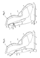
- Figures 4 and 5 illustrate another embodiment of the invention. Since most of the parts of the seat shown in Figures 4 and 5 are identical to corresponding parts shown in the seat shown in Figures 1 and 2, they are denoted by the same reference numerals and will not be described again in detail.
- the cylindrical member 62 is replaced by a cylindrical member 90 which has diametrically extending slots for the shoulder straps 40 and 42 of the child harness, similar to the slot 60 of Figures 1 to 3.
- the cylindrical member 90 is mounted on an axle 92 which is journaled in the beams 22 and 24 but does not project beyond the outside faces thereof.
- the cylindrical member 90 also carries a central pulley 94.
- a manually engageable clamp 96 for the shoulder strap 84 of the vehicle seat belt is mounted on the outer face of the beam 24 a short distance below the upper end of the opening 78 therein.
- the clamp 96 which may be as described in EP-A-0326265, is secured to the beam 24 by frangible means, such as plastic rivets arranged to yield when the force thereon extends a value unlikely to be encountered except in an accident.
- a flexible cable 98 such as a stranded steel wire, has one end 100 secured to the clamp 96. From there, it extends through the opening 78, round a guide pulley 102 mounted on the rear surface of the seat back 16, and thence round the pulley 94 to an anchorage 104 thereon.
- the load on the shoulder strap 84 of the vehicle seat belt pulls the clamp 96 away from the beam 24, breaking the frangible means.
- the shoulder strap 84 moves up to the top of the opening 78.
- the resulting movement of the flexible cable 98 causes angular movement of the cylindrical member 90 so as to tighten the shoulder straps 40 and 42 of the child harness.
- a second clamp 106 similar to the clamp 96, is mounted on the beam 22 on the other side of the seat.
- a flexible cable 108 has one end 110 secured to the clamp 106.
- the cable 108 is led round a guide pulley 112 and round the drum 94 to the anchorage point 104.
- the provision of two clamps 96 and 106 permits the seat to be used on either side of a vehicle.
- Figure 6 shows a modification of the seat shown in Figures 4 and 5 applicable for use where the vehicle shoulder strap 84 of the vehicle seat belt is attached to a pretensioner.
- the clamps 96 and 106 have been replaced by lock-off devices 120 and 122 which are permanently secured to the beams 22 and 24 and which are as described in EP-A-0200411, i.e. they block movement of the vehicle shoulder strap 84 towards the buckle tongue 74 while allowing movement in the opposite direction.
- the end 100 of the cable 98 is attached to a clamp 124, which is secured to the shoulder strap 84 above the lock-off device 122 but is not otherwise attached to the child seat.
- the shoulder strap 84 is pulled upwardly through the lock-off device 122 and the clamp pulls on the cable 98, causing rotation of the cylindrical member 90 to tighten the shoulder straps 40 and 42 of the child harness.
- the clamp 124 is unthreaded from the slot 78 in the beam 24 and threaded through the slot 76 in the beam 22.
- the cable 98 is lead round the pulley 112 instead of round the pulley 98.
- Figure 7 shows a child seat similar to the seat shown in Figures 1 to 3, but equipped with a pair of buckles 140 mounted on rigid links 142 projecting from the rear of the base 12 for engagement with rigid anchorage units on a vehicle as specified in ISO Standard ISO 13216-1:1999 Road Vehicles - Anchorages in Vehicles and Attachments for Child Restraint Systems - Part 1: Seat Bight Anchorages and Attachments.
- the child seat is also equipped with a V-shaped upper tether strap 144 of the type described in US-A-5630645. The ends of the tether strap extend round belt guides 146 near the top of the seat body 10 and thence through the slots 70 and 72 in the pulleys 66 and 68 respectively.
- Each slot 70, 72 contains a lock-off device of the type described in EP-A-0200411 arranged to block movement of the strap 144 towards the corresponding belt guide 146. Consequently, the tether strap 144 can be tightened by pulling on either end 148.
- the pulleys 66 and 68 of Figure 7 may be replaced by a single central pulley on the cylindrical member 62 to which a single tether strap is connected. Since this pulley is not accessible when the child seat is in position on a vehicle seat, it is necessary to provide a separate adjuster for tightening the tether strap.
- Figures 8 and 9 show another child seat similar to that shown in Figures 1 to 3.
- a foot 150 is mounted on a pivot axle 152 in an opening 154 in the base 12.
- a guide wall 156 extends above the opening 154.
- a wedge 158 is slidably mounted between the guide wall 156 and the foot 150 for movement between the position shown in Figure 8, in which the foot 150 is retracted into the base, and the position shown in Figure 9, in which the foot 150 projects downwardly below the base. In the latter position, the foot compresses the vehicle seat cushion below the child seat, thus reducing the extent of downward movement of the front part of the child seat.
- the wedge 155 is coupled to one end of a Bowden cable 160, the other end of which is wound on the cylindrical member 62. Rotation of the cylindrical member 62, as described above with reference to Figures 1 to 3, thus causes movement of the wedge 158 from the position shown in Figure 8 to the position shown in Figure 9. Return of the wedge to its original position is prevented by a ratchet mechanism (not shown).
- Figure 10 shows the application of the invention to a rearward facing child seat 170 having a base 172 resting on a vehicle seat 174 and secured in place by the lap strap 176 and shoulder strap 178 of a vehicle seat belt.
- the child seat 170 is equipped with a harness (not shown) similar to that described in EP-A-1006017.
- a manually actuable clamp 180 similar to the clamps 96 and 106, is secured to one side of the seat back 182 of the child seat 170 by frangible means such as plastic rivets.
- the clamp 180 is coupled to a mechanism similar to that described with reference to Figures 4 and 5.
- a second similar clamp (not shown) is provided on the other side of the seat 170.
- FIG 11 shows another rearward facing child seat 200 having a base 202 resting on a vehicle seat 204 and secured in place by a lap strap 206 and a shoulder strap 208 of a vehicle seat belt.
- An auxiliary panel 210 has a hinge 212 extending along its bottom edge. The hinge 212 is secured to the seat back 214 of the seat 200. In normal use, the panel 210 abuts against the seat back 214.
- a belt guide 216 for the shoulder strap 208 of the vehicle seat belt is secured on one end of a piston 218 which is slidably mounted in a hole in the seat back 214 so that its other end abuts against the inner surface of the auxiliary panel 210.
- the belt guide 216 and piston 218 are biased outwardly by a compression spring 220 so as to permit the auxiliary panel 210 to abut against the seat back 214.
- the spring 220 may be replaced by a frangible link which is arranged to break in the event of an accident. With this arrangement, the auxiliary panel 210 remains in the position shown in Figure 12 after tension in the shoulder strap 208 has reduced.
- FIG 13 shows a seat 230 which is a modified version of the seat 200 of Figures 11 and 12. Equivalent parts are denoted by the same reference numerals and will not be described in detail.
- the auxiliary panel 210 is driven to its deployed position in the event of an accident by a cam 232 which is mounted for rotation about a horizontal axis and coupled to pulleys (not shown), similar to the pulleys 66 and 68 of Figures 1 to 3.
- the shoulder strap 208 passes through the slot in one such pulley.
- Figure 14 shows a rearward facing child seat 240 mounted on a base 242 which rests on the vehicle seat 204 and is held in place by the lap strap 206 and the shoulder strap 208 of the vehicle seat belt.
- the body of the seat 240 is formed in two parts.
- a seat portion 244 is mounted on the base 242.
- a seat back 246 is pivotally mounted on the seat portion 244 by means of a pivot axle 248, with sufficient friction to hold the seat back 246 in the position illustrated. In the event of an accident causing increased tension in the shoulder strap 208, this friction is overcome so that the seat back 246 pivots about the axle 248 to a more upright position.
- a stop (not shown) limits the extent of such forward movement.
Abstract
Description
- This invention relates to a child safety seat for use in a vehicle of the type comprising a seat body including a seat portion and a seat back, and a link member for connecting the seat body to a vehicle body. The link member may comprise a guide adapted to be engaged by a vehicle seat belt. Alternatively, the link member may comprise a flexible or rigid coupling adapted to engage with anchorages on the vehicle body.
- Frequently, it is difficult for a child's body to be positioned in a child seat in conditions that are optimum in the event of an accident. For example, if the child seat has a child harness (such as is disclosed in EP-A-0295838), it is desirable for the harness to be as tight as possible. In practice, users do not tighten the harnesses of child seats sufficiently for optimum performance. In addition, the straps of such harnesses are liable to stretch during an accident.
- Similarly, in the case of a rearward-facing seat for an infant (such as is disclosed in EP-A-1006017), the optimum position in the event of an accident is to have the seat back in a relatively upright position. In normal use, a more reclined position is preferred because it provides better support for the infant's head and because it is more conducive to sleep.
- It is an object of this invention to provide a child safety seat in which these disadvantages are mitigated.
- According to the invention, in a child safety seat of the type described above, movement of the link member relative to the seat body being operative to cause movement of a part of the child seat relative to the child seat body so as to put the child seat in a better condition to protect a child occupant in the event of an accident.
- Drive means may be arranged to act on said part of the child seat in response to movement of the link member relative to the seat body.
- In one form of the invention the drive means is arranged to cause tightening of the child harness.
- In another from of the invention, the drive means is arranged to cause movement of at least part of the seat back relative to the seat body.
- The link member may be a flexible strap.
- When the invention is applied to a child safety seat of the type adapted to be secured on a vehicle seat by a three-point seat belt, the function of the link member may be performed by the shoulder strap of the three-point belt or by a separate upper tether strap.
- The drive means may include a cylindrical member journaled for rotation about a horizontal axis located behind the seat back and having diametrically extended slots through which the shoulder straps of the child harness project. In normal use, these slots are oriented so as to be substantially parallel to the normal path of such shoulder straps. In the event of an accident, the strap connected to the vehicle is arranged to cause rotation of the cylindrical member so as to wind the shoulder straps of the child harness therearound.
- The coupling between the strap connected to the vehicle and the cylindrical member may comprise a pulley mounted on one end of the cylindrical member and secured for simultaneous rotation therewith. The pulley has a diametrically extending slot through which the strap connected to the vehicle extends. In normal use, this slot is at right angles to the normal path of such strap so that when a tightening force is applied to the strap, it tends to cause rotation of the pulley and the cylindrical member.
- In another form of the invention, the strap connected to the vehicle is secured in a clamp which is attached to the child seat by a frangible link which is arranged to yield in the event of an accident. The clamp is also connected to a flexible member such as a steel wire which is wrapped around a pulley on the cylindrical member.
- In the event that the frangible link breaks, the steel wire causes rotation of the cylindrical member as the clamp is pulled away from the child seat.
- The invention is applicable both to forward-facing and to rearward-facing child seats. It has particular application to vehicles in which the vehicle seat belts are equipped with pyrotechnic tensioners.
- Embodiments of the invention will now be described, by way of example, with reference to the accompanying drawings, in which:
- Figure 1 is a rear elevation of a child seat in accordance with the first embodiment of the invention;
- Figure 2 is a side view of the child seat shown in Figure 1;
- Figure 3 is a cross-sectional view taken on the line 3-3 in Figure 1;
- Figure 4 is a rear elevation of a child seat in accordance with a second embodiment of the invention;
- Figure 5 is a side view of the child seat shown in Figure 4;
- Figure 6 is a rear elevation of a child seat in accordance with a third embodiment of the invention;
- Figure 7 is a side view, similar to Figure 2 of a child seat in accordance with a fourth embodiment of the invention;
- Figure 8 is a longitudinal cross-sectional view taken on the centre line of a child seat in accordance with a fifth embodiment of the invention prior to an accident;
- Figure 9 is a longitudinal cross-sectional view taken on the centre line of the child seat shown in Figure 8, after an accident;
- Figure 10 is a side view of a child seat in accordance with a sixth embodiment of the invention;
- Figure 11 is a longitudinal cross-sectional view taken on the centre line of a child seat in accordance with a seventh embodiment of the invention prior to an accident;
- Figure 12 is a longitudinal cross-sectional view taken on the centre line of the child seat shown in Figure 11, after an accident;
- Figure 13 is a longitudinal cross-sectional view taken on the centre line of a child seat in accordance with an eighth embodiment of the invention prior to an accident; and
- Figure 14 is a longitudinal cross-sectional view taken on the centre line of a child seat in accordance with a ninth embodiment of the invention prior to an accident.
-
- Referring to Figures 1 to 3, a child safety seat comprises a
body 10 and abase 12. Thebody 10 is formed as a one-piece plastics moulding and has aseat portion 14, seat backportion 16 andside walls beams side wall portions - The
base 12 has a pair ofupstanding walls beams body 10. Thebase 12 also has a pair of upwardly projectingsupport members beams stub axles beams body 10 to thebase 12. A recline mechanism (not shown), which may be as described in EP-A-0732235, controls angular movement of thebody 10 relative to thebase 12. - The
body 10 is fitted with a conventional harness for a child occupant, consisting of a pair ofshoulder straps lap strap 44 is visible in Figure 3, and acrutch strap 46. Thestraps buckle 48. Theseat back portion 16 has three sets ofslots shoulder straps shoulder straps yoke 56 which is in turn connected to anadjuster strap 58 extending to astrap adjuster 60 mounted on theseat body 10 below the front edge of theseat portion 14. - In accordance with the invention, the paths of the
shoulder straps slots 50 and theyoke 56, are through respective diametrically extending slots 60 (Figure 3) in aroller 62 which is secured to anaxle 64. Theaxle 64 is journaled on thebeams respective pulley pulley sided slot slots 60 in theroller 62. - When the child seat is to be installed on a vehicle seat, the
tongue 74 of the vehicle seat belt is passed throughrespective openings beams tongue 74 is then inserted into itsbuckle 80. Thelap strap 82 and theshoulder strap 84 thus both pass through theopenings shoulder strap 84 is pulled tight, so as to take all slack out of thelap strap 82, and secured by a manuallyengageable clamp 86 which is mounted on the outer face of thebeam 24 in alignment with the upper end of theopening 78 therein. Theclamp 86 may be as described in EP-A-0326265. - After emerging from the
clamp 86, theshoulder strap 84 is lead through theslot 70 in thepulley 66, as can best be seen in Figures 1 and 2. Aturnbuckle catch 88 on the end face of thepulley 66 is moved counter-clockwise from the orientation shown in Figure 2 to a position in which it extends across theslot 70 so as to retain theshoulder strap 84 therein. - After the child seat has been installed on the vehicle seat, a child may be placed in the
seat body 10. After the harness has been fitted and thebuckle 48 fastened, theadjuster strap 58 is pulled outwards through theadjuster 60 to tighten the harness. Theroller 62 may be spring-biased in the counter-clockwise direction (as viewed in Figure 3) to a position in which theslot 60 is horizontal. Tightening the child harness causes clockwise rotation of theroller 62. The resulting movement of thepulleys 66 and 68 (which draws additional shoulder strap webbing from the vehicle seat belt retractor) can be used to provide a visual indication that the child harness has been tightened adequately. - In the event of a front-impact accident, the
child seat 10 starts to move forwards relative to the vehicle before the body of a child occupant moves forwards relative to thechild seat 10. The resulting tension in theshoulder strap 84 causes thepulley 66 and, with it, thecylindrical member 62, to turn through 90° in the counter-clockwise direction as viewed in Figure 2, thus wrapping part of the shoulder straps 40 and 42 of the child harness round thecylinder 62 and pulling the child firmly back against the seat back 16 of the child seat. This reduces undesirable forward head excursion. Since the diameter of thepulleys roller 62, the shoulder straps 40 and 42 remain wound on theroller 62 even when the child's body has moved forwards to its maximum excursion. - The
roller 62 may be provided with a ratchet to prevent motion in the clockwise direction, in which case the diameter of thepulleys roller 62. However, with this arrangement, it is not possible for theroller 62 to be spring-biased in the counter-clockwise direction in order to provide a visual indication that the child harness has been tightened adequately. - If the vehicle in which the child seat is installed is equipped with a pyrotechnic pretensioner (or other similar stored-energy device) for the vehicle seat belt, actuation of such pretensioner in an accident will cause the tension in the
shoulder strap 84 of the vehicle seat belt to turn thepulley 66 through 90° before thechild seat body 10 starts to move forwards, thus tightening the shoulder straps 40 and 42 of the child seat harness to hold the child firmly back in the seat at the same time as thechild seat body 10 is pulled backwards against the vehicle seat by theshoulder strap 84. - Instead of being routed through the
slots 50, the shoulder straps 40 and 42 of the child harness may be routed to theroller 62 through either theslots 52 or theslots 54. It is preferable for theroller 62 to be positioned level with thehighest slots 50 because the need to pull the child's body firmly back into thechild seat 10 is greater for a larger child than for a relatively small one. - The
clamp 86 may be replaced by a lock-off device having a cam bar, as described in EP-A-0200411, located in theslot 70 in thepulley 66. Thepulley 66 may be held in the orientation shown in Figures 1 and 2 by a frangible link so as to prevent tension in thelap strap 82 causing rotation of thepulley 66 in normal use. The frangible link is arranged to fail under the load imposed during an accident. - Figures 4 and 5 illustrate another embodiment of the invention. Since most of the parts of the seat shown in Figures 4 and 5 are identical to corresponding parts shown in the seat shown in Figures 1 and 2, they are denoted by the same reference numerals and will not be described again in detail. In Figures 4 and 5, the
cylindrical member 62 is replaced by acylindrical member 90 which has diametrically extending slots for the shoulder straps 40 and 42 of the child harness, similar to theslot 60 of Figures 1 to 3. Thecylindrical member 90 is mounted on anaxle 92 which is journaled in thebeams cylindrical member 90 also carries acentral pulley 94. - A manually
engageable clamp 96 for theshoulder strap 84 of the vehicle seat belt is mounted on the outer face of the beam 24 a short distance below the upper end of theopening 78 therein. Theclamp 96, which may be as described in EP-A-0326265, is secured to thebeam 24 by frangible means, such as plastic rivets arranged to yield when the force thereon extends a value unlikely to be encountered except in an accident. Aflexible cable 98, such as a stranded steel wire, has oneend 100 secured to theclamp 96. From there, it extends through theopening 78, round aguide pulley 102 mounted on the rear surface of the seat back 16, and thence round thepulley 94 to ananchorage 104 thereon. In the event of a front-impact accident, the load on theshoulder strap 84 of the vehicle seat belt pulls theclamp 96 away from thebeam 24, breaking the frangible means. Theshoulder strap 84 moves up to the top of theopening 78. The resulting movement of theflexible cable 98 causes angular movement of thecylindrical member 90 so as to tighten the shoulder straps 40 and 42 of the child harness. - A
second clamp 106, similar to theclamp 96, is mounted on thebeam 22 on the other side of the seat. Aflexible cable 108 has oneend 110 secured to theclamp 106. Thecable 108 is led round aguide pulley 112 and round thedrum 94 to theanchorage point 104. The provision of twoclamps - Figure 6 shows a modification of the seat shown in Figures 4 and 5 applicable for use where the
vehicle shoulder strap 84 of the vehicle seat belt is attached to a pretensioner. Theclamps devices beams vehicle shoulder strap 84 towards thebuckle tongue 74 while allowing movement in the opposite direction. Theend 100 of thecable 98 is attached to aclamp 124, which is secured to theshoulder strap 84 above the lock-offdevice 122 but is not otherwise attached to the child seat. In the event of actuation of the pretensioner, theshoulder strap 84 is pulled upwardly through the lock-offdevice 122 and the clamp pulls on thecable 98, causing rotation of thecylindrical member 90 to tighten the shoulder straps 40 and 42 of the child harness. - When it is desired to use the seat child seat of Figure 6 on the other side of the vehicle, with the vehicle shoulder strap engaged by the lock-off
device 120, theclamp 124 is unthreaded from theslot 78 in thebeam 24 and threaded through theslot 76 in thebeam 22. Thecable 98 is lead round thepulley 112 instead of round thepulley 98. - Figure 7 shows a child seat similar to the seat shown in Figures 1 to 3, but equipped with a pair of
buckles 140 mounted onrigid links 142 projecting from the rear of thebase 12 for engagement with rigid anchorage units on a vehicle as specified in ISO Standard ISO 13216-1:1999 Road Vehicles - Anchorages in Vehicles and Attachments for Child Restraint Systems - Part 1: Seat Bight Anchorages and Attachments. The child seat is also equipped with a V-shapedupper tether strap 144 of the type described in US-A-5630645. The ends of the tether strap extend round belt guides 146 near the top of theseat body 10 and thence through theslots pulleys slot strap 144 towards the correspondingbelt guide 146. Consequently, thetether strap 144 can be tightened by pulling on eitherend 148. - The
pulleys cylindrical member 62 to which a single tether strap is connected. Since this pulley is not accessible when the child seat is in position on a vehicle seat, it is necessary to provide a separate adjuster for tightening the tether strap. - Figures 8 and 9 show another child seat similar to that shown in Figures 1 to 3. A
foot 150 is mounted on apivot axle 152 in anopening 154 in thebase 12. Aguide wall 156 extends above theopening 154. Awedge 158 is slidably mounted between theguide wall 156 and thefoot 150 for movement between the position shown in Figure 8, in which thefoot 150 is retracted into the base, and the position shown in Figure 9, in which thefoot 150 projects downwardly below the base. In the latter position, the foot compresses the vehicle seat cushion below the child seat, thus reducing the extent of downward movement of the front part of the child seat. - The wedge 155 is coupled to one end of a
Bowden cable 160, the other end of which is wound on thecylindrical member 62. Rotation of thecylindrical member 62, as described above with reference to Figures 1 to 3, thus causes movement of thewedge 158 from the position shown in Figure 8 to the position shown in Figure 9. Return of the wedge to its original position is prevented by a ratchet mechanism (not shown). - Figure 10 shows the application of the invention to a rearward facing
child seat 170 having a base 172 resting on avehicle seat 174 and secured in place by thelap strap 176 andshoulder strap 178 of a vehicle seat belt. Thechild seat 170 is equipped with a harness (not shown) similar to that described in EP-A-1006017. A manuallyactuable clamp 180, similar to theclamps child seat 170 by frangible means such as plastic rivets. Theclamp 180 is coupled to a mechanism similar to that described with reference to Figures 4 and 5. A second similar clamp (not shown) is provided on the other side of theseat 170. - Any of the mechanisms described above may be used with a rearward facing seat.
- Figure 11 shows another rearward facing
child seat 200 having a base 202 resting on avehicle seat 204 and secured in place by alap strap 206 and ashoulder strap 208 of a vehicle seat belt. Anauxiliary panel 210 has ahinge 212 extending along its bottom edge. Thehinge 212 is secured to the seat back 214 of theseat 200. In normal use, thepanel 210 abuts against the seat back 214. - A
belt guide 216 for theshoulder strap 208 of the vehicle seat belt is secured on one end of apiston 218 which is slidably mounted in a hole in the seat back 214 so that its other end abuts against the inner surface of theauxiliary panel 210. Thebelt guide 216 andpiston 218 are biased outwardly by acompression spring 220 so as to permit theauxiliary panel 210 to abut against the seat back 214. - In the event of an accident causing increased tension in the
shoulder strap 208, thebelt guide 216 andpiston 218 are pushed inwardly through the seat back 214, against the action of thespring 220, pushing theauxiliary panel 210 to the position shown in Figure 12. This puts a child occupant of the seat in a more upright position so that the seat is better placed to counteract the effect of horizontal inertial forces on the child's head. - The
spring 220 may be replaced by a frangible link which is arranged to break in the event of an accident. With this arrangement, theauxiliary panel 210 remains in the position shown in Figure 12 after tension in theshoulder strap 208 has reduced. - Figure 13 shows a
seat 230 which is a modified version of theseat 200 of Figures 11 and 12. Equivalent parts are denoted by the same reference numerals and will not be described in detail. In place of thebelt guide 216 andpiston 218, theauxiliary panel 210 is driven to its deployed position in the event of an accident by acam 232 which is mounted for rotation about a horizontal axis and coupled to pulleys (not shown), similar to thepulleys shoulder strap 208 passes through the slot in one such pulley. - Figure 14 shows a rearward facing
child seat 240 mounted on a base 242 which rests on thevehicle seat 204 and is held in place by thelap strap 206 and theshoulder strap 208 of the vehicle seat belt. The body of theseat 240 is formed in two parts. Aseat portion 244 is mounted on thebase 242. A seat back 246 is pivotally mounted on theseat portion 244 by means of apivot axle 248, with sufficient friction to hold the seat back 246 in the position illustrated. In the event of an accident causing increased tension in theshoulder strap 208, this friction is overcome so that the seat back 246 pivots about theaxle 248 to a more upright position. A stop (not shown) limits the extent of such forward movement.
Claims (13)
- A child safety seat comprising a seat body (10) including a seat portion (14) and a seat back (16), and in a link member (84, 144, 178, 208) for connecting the seat body (10) to a vehicle body, characterised in that movement of the link member (84, 144, 178, 208) relative to the seat body (10) is operative to cause movement of a part (40, 42, 158, 210, 246) of the child seat relative to the child seat body (10) so as to put the child seat in a better condition to protect a child occupant in the event of an accident.
- A child safety seat according to claim 1, further comprising drive means (62, 90, 218, 232) acting on said part (40, 42, 158, 210, 246) of the child seat in response to movement of the link member (84, 144, 178, 208) relative to the seat body (10).
- A child safety seat according to claim 2, wherein the link member comprises a flexible strap (84, 144, 178, 208).
- A child safety seat according to claim 3, wherein the flexible strap comprises a shoulder strap (84, 178, 208) of a vehicle seat belt.
- A child safety seat according to claim 3, wherein the flexible strap comprises a tether strap (144) adapted to extend from the upper region of the child seat back (16) to a fixed point on a vehicle.
- A child safety seat according to claim 3, 4 or 5, wherein the drive means includes a pulley (66, 68) having a diametrically extending slot (70, 72) through which the strap (84, 144) extends.
- A child safety seat according to any of claims 2 to 5, having a harness secured to the seat body (10) for engaging round the torso of a child occupant of the seat, wherein the harness includes at least one strap (66, 68) projecting through a slot (50, 52, 54) in the seat body (10), and the drive means (62, 90) is arranged to cause tightening of the child harness.
- A child safety seat according to claim 7, wherein the drive means comprises a cylindrical member (62, 90) journaled for rotation about a horizontal axis locate8 behind the seat back (16) and having diametrically extended slots (60) through which the shoulder straps (40, 42) of the child harness project.
- A child safety seat according to any preceding claim, wherein the link member (84) is secured in a clamp (96, 106, 124) which is connected by a flexible member (100) to said drive means (90).
- A child safety seat according to claim 9, wherein the clamp (96, 106) is attached to the child seat by a frangible link which is arranged to yield in the event of an accident.
- A child safety seat according to claim 1 or 2, wherein the link member (178, 208) is arranged to cause movement of at least part of the seat back relative to the seat body (10).
- A child seat according to claim 11, adapted to face rearwardly in a vehicle, wherein the link member (178, 208) is arranged to cause pivotal movement of at last part (210, 246) of the seat back rearwardly in the vehicle about its bottom edge (212, 248).
- A child safety seat according to claim 11 or 12, wherein the link comprises a shoulder strap (178, 208) of a vehicle seat belt.
Applications Claiming Priority (4)
| Application Number | Priority Date | Filing Date | Title |
|---|---|---|---|
| GBGB0120247.2A GB0120247D0 (en) | 2001-08-21 | 2001-08-21 | Child safety seat |
| GB0120247 | 2001-08-21 | ||
| GBGB0124640.4A GB0124640D0 (en) | 2001-08-21 | 2001-10-15 | Child safety seat |
| GB0124640 | 2001-10-15 |
Publications (2)
| Publication Number | Publication Date |
|---|---|
| EP1285810A1 true EP1285810A1 (en) | 2003-02-26 |
| EP1285810B1 EP1285810B1 (en) | 2007-11-07 |
Family
ID=26246451
Family Applications (1)
| Application Number | Title | Priority Date | Filing Date |
|---|---|---|---|
| EP02255435A Expired - Lifetime EP1285810B1 (en) | 2001-08-21 | 2002-08-02 | Child safety seat |
Country Status (5)
| Country | Link |
|---|---|
| US (1) | US20030047972A1 (en) |
| EP (1) | EP1285810B1 (en) |
| JP (1) | JP2003137010A (en) |
| AT (1) | ATE377522T1 (en) |
| ES (1) | ES2295290T3 (en) |
Cited By (11)
| Publication number | Priority date | Publication date | Assignee | Title |
|---|---|---|---|---|
| WO2005120910A1 (en) * | 2004-06-09 | 2005-12-22 | Britax Childcare Pty Ltd | Child safety seat, shell and harness |
| EP1717096A2 (en) | 2005-04-29 | 2006-11-02 | HTS Hans Torgersen & Sonn AS | Children's safety seat with guide and tension device |
| DE102005037826A1 (en) * | 2005-08-08 | 2007-02-15 | Grammer Ag | Vehicle seat e .g. for children, has backrest and quick release mechanism as well as strap arrangement with straps having shoulder belt arranged within upper range of backrest |
| DE102005056124B4 (en) * | 2005-08-08 | 2007-10-31 | Grammer Ag | vehicle seat |
| ITMO20090116A1 (en) * | 2009-05-06 | 2010-11-07 | Segrall S R L | SEAT TO TRANSPORT A CHILD IN A VEHICLE. |
| AU2005251826B2 (en) * | 2004-06-09 | 2012-04-26 | Britax Childcare Pty Ltd | Child safety seat, shell and harness |
| KR20140010906A (en) * | 2012-07-17 | 2014-01-27 | 브리택스 차일드케어 프로프라이어터리 리미티드 | Improved tether strap arrangement |
| AU2012202655B2 (en) * | 2004-06-09 | 2014-11-27 | Britax Childcare Pty Ltd | Child safety seat, shell and harness |
| FR3010010A1 (en) * | 2013-08-30 | 2015-03-06 | Dorel France Sa | CAR SEAT FOR CHILDREN WITH OPTIMIZED REINFORCEMENT GROOVES |
| CN105034871A (en) * | 2015-07-10 | 2015-11-11 | 苍安国 | Device for restraining child passenger on motor vehicle |
| EP3498527A1 (en) * | 2017-12-14 | 2019-06-19 | BRITAX RÖMER Kindersicherheit GmbH | Child safety seat |
Families Citing this family (18)
| Publication number | Priority date | Publication date | Assignee | Title |
|---|---|---|---|---|
| DE10251040B4 (en) * | 2002-11-02 | 2010-01-21 | Daimler Ag | Child seat |
| CA2541310C (en) | 2003-10-10 | 2013-08-06 | Indiana Mills & Manufacturing, Inc. | Vehicle safety restraint system |
| WO2006004896A2 (en) * | 2004-06-29 | 2006-01-12 | Kidnetik Corp. | Child restraint apparatus for a vehicle |
| DE102005025570B4 (en) * | 2005-06-03 | 2008-05-29 | Daimler Ag | Child seat for vehicles |
| US20080012401A1 (en) * | 2006-05-09 | 2008-01-17 | Britax Child Safety, Inc. | Energy absorbing tether for child safety seat |
| US7547065B2 (en) * | 2007-02-23 | 2009-06-16 | Evenflo Company, Inc. | Child vehicle seat with harness adjustment mechanism |
| US7717506B2 (en) * | 2007-12-12 | 2010-05-18 | Britax Child Safety, Inc. | Child restraint apparatus for vehicle |
| FR2952592B1 (en) * | 2009-11-16 | 2011-12-30 | Dorel France Sa | CAR SEAT FOR REVERSIBLE CHILD WITH UNIQUE STRAPPING. |
| US8434827B2 (en) * | 2010-07-26 | 2013-05-07 | Mattel, Inc. | Infant support structure with polymer coated restraint straps |
| CL2012001772A1 (en) * | 2011-07-01 | 2014-06-06 | Wonderland Nursery Goods | A child seat comprising a seat frame with a back, an anchor band that has an intermediate portion and two end portions respectively provided with two operable fasteners for fixing with an anchor structure of a vehicle, and operable closure . |
| EP2546096B1 (en) * | 2011-07-14 | 2013-09-11 | Volvo Car Corporation | Child seat |
| CN102951045A (en) * | 2011-08-31 | 2013-03-06 | 常州博万达汽车安全设备有限公司 | Child safety seat capable of being installed and used in two directions and installation method |
| CA2941448A1 (en) * | 2013-03-14 | 2014-10-02 | Phillip Love | Child seat with impact dispersal device |
| KR101382542B1 (en) * | 2013-08-20 | 2014-04-07 | 김정율 | Infant seat belt |
| DE202015107068U1 (en) * | 2015-12-23 | 2016-01-20 | Cybex Gmbh | Child seat for attachment to a motor vehicle seat |
| US10384570B2 (en) * | 2017-04-18 | 2019-08-20 | Ford Global Technologies, Llc | Child-seat restraint system |
| US10661749B2 (en) * | 2017-11-08 | 2020-05-26 | Hoon Y. Kim | Adjustable restraint system |
| US11820322B1 (en) | 2022-05-17 | 2023-11-21 | Hoonyoung Kim | Restraint system |
Citations (10)
| Publication number | Priority date | Publication date | Assignee | Title |
|---|---|---|---|---|
| DE2712917A1 (en) * | 1977-03-24 | 1978-09-28 | Cocinel Kindergeraete Und Auss | Safety belt for child's car seat - has separate seat shell fastening to support its inertial force in collision |
| EP0200411A2 (en) * | 1985-05-01 | 1986-11-05 | Britax-Excelsior Limited | Child's safety seat |
| EP0295838A1 (en) * | 1987-06-17 | 1988-12-21 | Britax Child-Care Products Pty Ltd. | Harness adjuster for child's seat |
| EP0326265A2 (en) * | 1988-01-26 | 1989-08-02 | Britax-Excelsior Limited | Child's safety seat |
| EP0554807A2 (en) * | 1992-01-31 | 1993-08-11 | Life Force Associates L.P. | Child safety seat |
| EP0732235A2 (en) * | 1995-02-18 | 1996-09-18 | BRITAX RÖMER Kindersicherheit GmbH | Child safety seat |
| US5630645A (en) * | 1994-08-01 | 1997-05-20 | Britax Child-Care Products Pty Ltd. | Safety seat tether strap |
| EP0805066A2 (en) * | 1996-05-03 | 1997-11-05 | TRW Occupant Restraint Systems GmbH | Childrens' seat for vehicles |
| EP1006017A2 (en) * | 1998-12-04 | 2000-06-07 | Britax Excelsior Limited | Child safety seat |
| WO2001034428A1 (en) * | 1999-11-05 | 2001-05-17 | Igc (Australia) Pty Ltd | Improved child restraints |
-
2002
- 2002-08-02 AT AT02255435T patent/ATE377522T1/en not_active IP Right Cessation
- 2002-08-02 EP EP02255435A patent/EP1285810B1/en not_active Expired - Lifetime
- 2002-08-02 ES ES02255435T patent/ES2295290T3/en not_active Expired - Lifetime
- 2002-08-15 US US10/219,621 patent/US20030047972A1/en not_active Abandoned
- 2002-08-21 JP JP2002240151A patent/JP2003137010A/en not_active Withdrawn
Patent Citations (10)
| Publication number | Priority date | Publication date | Assignee | Title |
|---|---|---|---|---|
| DE2712917A1 (en) * | 1977-03-24 | 1978-09-28 | Cocinel Kindergeraete Und Auss | Safety belt for child's car seat - has separate seat shell fastening to support its inertial force in collision |
| EP0200411A2 (en) * | 1985-05-01 | 1986-11-05 | Britax-Excelsior Limited | Child's safety seat |
| EP0295838A1 (en) * | 1987-06-17 | 1988-12-21 | Britax Child-Care Products Pty Ltd. | Harness adjuster for child's seat |
| EP0326265A2 (en) * | 1988-01-26 | 1989-08-02 | Britax-Excelsior Limited | Child's safety seat |
| EP0554807A2 (en) * | 1992-01-31 | 1993-08-11 | Life Force Associates L.P. | Child safety seat |
| US5630645A (en) * | 1994-08-01 | 1997-05-20 | Britax Child-Care Products Pty Ltd. | Safety seat tether strap |
| EP0732235A2 (en) * | 1995-02-18 | 1996-09-18 | BRITAX RÖMER Kindersicherheit GmbH | Child safety seat |
| EP0805066A2 (en) * | 1996-05-03 | 1997-11-05 | TRW Occupant Restraint Systems GmbH | Childrens' seat for vehicles |
| EP1006017A2 (en) * | 1998-12-04 | 2000-06-07 | Britax Excelsior Limited | Child safety seat |
| WO2001034428A1 (en) * | 1999-11-05 | 2001-05-17 | Igc (Australia) Pty Ltd | Improved child restraints |
Cited By (21)
| Publication number | Priority date | Publication date | Assignee | Title |
|---|---|---|---|---|
| AU2012202655B2 (en) * | 2004-06-09 | 2014-11-27 | Britax Childcare Pty Ltd | Child safety seat, shell and harness |
| US7552969B2 (en) | 2004-06-09 | 2009-06-30 | Britax Childcare Pty Ltd | Child safety seat, shell and harness |
| AU2005251826B2 (en) * | 2004-06-09 | 2012-04-26 | Britax Childcare Pty Ltd | Child safety seat, shell and harness |
| WO2005120910A1 (en) * | 2004-06-09 | 2005-12-22 | Britax Childcare Pty Ltd | Child safety seat, shell and harness |
| EP1717096A2 (en) | 2005-04-29 | 2006-11-02 | HTS Hans Torgersen & Sonn AS | Children's safety seat with guide and tension device |
| EP2077202A2 (en) | 2005-04-29 | 2009-07-08 | HTS Hans Torgersen & Sonn AS | Children's safety seat with guide and tension device |
| US7837264B2 (en) | 2005-04-29 | 2010-11-23 | Hts Hans Torgersen & Sons As | Children's safety seat with guide and tension device |
| DE102005037826A1 (en) * | 2005-08-08 | 2007-02-15 | Grammer Ag | Vehicle seat e .g. for children, has backrest and quick release mechanism as well as strap arrangement with straps having shoulder belt arranged within upper range of backrest |
| DE102005037826B4 (en) * | 2005-08-08 | 2007-08-30 | Grammer Ag | vehicle seat |
| DE102005056124B4 (en) * | 2005-08-08 | 2007-10-31 | Grammer Ag | vehicle seat |
| ITMO20090116A1 (en) * | 2009-05-06 | 2010-11-07 | Segrall S R L | SEAT TO TRANSPORT A CHILD IN A VEHICLE. |
| KR20140010906A (en) * | 2012-07-17 | 2014-01-27 | 브리택스 차일드케어 프로프라이어터리 리미티드 | Improved tether strap arrangement |
| CN103538553A (en) * | 2012-07-17 | 2014-01-29 | 宝得适儿童用品有限公司 | Improved tether strap arrangement |
| CN103538554A (en) * | 2012-07-17 | 2014-01-29 | 宝得适儿童用品有限公司 | An improved tensioning arrangement for a child restraint |
| KR20140010907A (en) * | 2012-07-17 | 2014-01-27 | 브리택스 차일드케어 프로프라이어터리 리미티드 | A tensioning arrangement for a child restraint |
| CN103538553B (en) * | 2012-07-17 | 2017-03-01 | 宝得适儿童用品有限公司 | Take-up device for children's restraint system |
| CN103538554B (en) * | 2012-07-17 | 2017-05-24 | 宝得适儿童用品有限公司 | An improved tensioning arrangement for a child restraint |
| EP2687401A3 (en) * | 2012-07-17 | 2017-12-27 | Britax Childcare Pty Ltd. | A tensioning arrangement for a child restraint |
| FR3010010A1 (en) * | 2013-08-30 | 2015-03-06 | Dorel France Sa | CAR SEAT FOR CHILDREN WITH OPTIMIZED REINFORCEMENT GROOVES |
| CN105034871A (en) * | 2015-07-10 | 2015-11-11 | 苍安国 | Device for restraining child passenger on motor vehicle |
| EP3498527A1 (en) * | 2017-12-14 | 2019-06-19 | BRITAX RÖMER Kindersicherheit GmbH | Child safety seat |
Also Published As
| Publication number | Publication date |
|---|---|
| US20030047972A1 (en) | 2003-03-13 |
| JP2003137010A (en) | 2003-05-14 |
| ATE377522T1 (en) | 2007-11-15 |
| ES2295290T3 (en) | 2008-04-16 |
| EP1285810B1 (en) | 2007-11-07 |
Similar Documents
| Publication | Publication Date | Title |
|---|---|---|
| EP1285810B1 (en) | Child safety seat | |
| US20080303325A1 (en) | Child Seat for Vehicles | |
| US7648199B2 (en) | Energy absorbing tether for child safety seat | |
| CA2248472C (en) | Wheelchair restraint system for a transportation vehicle | |
| EP0936980B1 (en) | Vehicle seat | |
| AU2013202975B2 (en) | Seat belt lock-off for a safety seat | |
| US20060163923A1 (en) | Child seat | |
| US7278684B2 (en) | Retractable coupling apparatus | |
| US6024408A (en) | Apparatus and method for installation of a child car seat in an automobile | |
| US6543846B2 (en) | Child car seat having one tethered belt | |
| CN111873866B (en) | Child safety seat with motorized forked belt tensioner | |
| EP0553062A2 (en) | Automatic locking tether for vehicle seat | |
| US6902195B2 (en) | Seat belt pretensioner | |
| JP2002079859A (en) | Fitting of child shoulder harness to auxiliary seat | |
| KR102120986B1 (en) | A tensioning arrangement for a child restraint | |
| US20020043836A1 (en) | Tether strap that allows rotation of a safety seat about a vertical axis | |
| US4763924A (en) | Seat movement responsive belt tensioning arm | |
| US3981535A (en) | Single retractor continuous loop restraint system | |
| EP3112209B1 (en) | Child safety seat with a device for pretensioning integrated safety belts restraining a child in the seat | |
| US7367630B2 (en) | Integrated seat of an automotive vehicle | |
| CN213501951U (en) | Vehicle seat for a vehicle and vehicle | |
| US20230242063A1 (en) | Automotive restraining belt and protective device therefor | |
| KR100321425B1 (en) | Structure of seat frame for automobile | |
| GB2389821A (en) | Seat-belt arrangement | |
| KR100288304B1 (en) | Load control device of car seat belt |
Legal Events
| Date | Code | Title | Description |
|---|---|---|---|
| PUAI | Public reference made under article 153(3) epc to a published international application that has entered the european phase |
Free format text: ORIGINAL CODE: 0009012 |
|
| AK | Designated contracting states |
Kind code of ref document: A1 Designated state(s): AT BE BG CH CY CZ DE DK EE ES FI FR GB GR IE IT LI LU MC NL PT SE SK TR |
|
| AX | Request for extension of the european patent |
Extension state: AL LT LV MK RO SI |
|
| 17P | Request for examination filed |
Effective date: 20030809 |
|
| AKX | Designation fees paid |
Designated state(s): AT BE BG CH CY CZ DE DK EE ES FI FR GB GR IE IT LI LU MC NL PT SE SK TR |
|
| GRAP | Despatch of communication of intention to grant a patent |
Free format text: ORIGINAL CODE: EPIDOSNIGR1 |
|
| RAP1 | Party data changed (applicant data changed or rights of an application transferred) |
Owner name: BRITAX EXCELSIOR LIMITED |
|
| GRAS | Grant fee paid |
Free format text: ORIGINAL CODE: EPIDOSNIGR3 |
|
| GRAA | (expected) grant |
Free format text: ORIGINAL CODE: 0009210 |
|
| AK | Designated contracting states |
Kind code of ref document: B1 Designated state(s): AT BE BG CH CY CZ DE DK EE ES FI FR GB GR IE IT LI LU MC NL PT SE SK TR |
|
| REG | Reference to a national code |
Ref country code: GB Ref legal event code: FG4D |
|
| REG | Reference to a national code |
Ref country code: IE Ref legal event code: FG4D |
|
| REG | Reference to a national code |
Ref country code: CH Ref legal event code: EP |
|
| REF | Corresponds to: |
Ref document number: 60223320 Country of ref document: DE Date of ref document: 20071220 Kind code of ref document: P |
|
| REG | Reference to a national code |
Ref country code: SE Ref legal event code: TRGR |
|
| ET | Fr: translation filed | ||
| REG | Reference to a national code |
Ref country code: ES Ref legal event code: FG2A Ref document number: 2295290 Country of ref document: ES Kind code of ref document: T3 |
|
| PG25 | Lapsed in a contracting state [announced via postgrant information from national office to epo] |
Ref country code: CH Free format text: LAPSE BECAUSE OF FAILURE TO SUBMIT A TRANSLATION OF THE DESCRIPTION OR TO PAY THE FEE WITHIN THE PRESCRIBED TIME-LIMIT Effective date: 20071107 Ref country code: LI Free format text: LAPSE BECAUSE OF FAILURE TO SUBMIT A TRANSLATION OF THE DESCRIPTION OR TO PAY THE FEE WITHIN THE PRESCRIBED TIME-LIMIT Effective date: 20071107 |
|
| PG25 | Lapsed in a contracting state [announced via postgrant information from national office to epo] |
Ref country code: BG Free format text: LAPSE BECAUSE OF FAILURE TO SUBMIT A TRANSLATION OF THE DESCRIPTION OR TO PAY THE FEE WITHIN THE PRESCRIBED TIME-LIMIT Effective date: 20080207 |
|
| REG | Reference to a national code |
Ref country code: CH Ref legal event code: PL |
|
| PG25 | Lapsed in a contracting state [announced via postgrant information from national office to epo] |
Ref country code: AT Free format text: LAPSE BECAUSE OF FAILURE TO SUBMIT A TRANSLATION OF THE DESCRIPTION OR TO PAY THE FEE WITHIN THE PRESCRIBED TIME-LIMIT Effective date: 20071107 |
|
| PG25 | Lapsed in a contracting state [announced via postgrant information from national office to epo] |
Ref country code: CZ Free format text: LAPSE BECAUSE OF FAILURE TO SUBMIT A TRANSLATION OF THE DESCRIPTION OR TO PAY THE FEE WITHIN THE PRESCRIBED TIME-LIMIT Effective date: 20071107 Ref country code: DK Free format text: LAPSE BECAUSE OF FAILURE TO SUBMIT A TRANSLATION OF THE DESCRIPTION OR TO PAY THE FEE WITHIN THE PRESCRIBED TIME-LIMIT Effective date: 20071107 |
|
| PG25 | Lapsed in a contracting state [announced via postgrant information from national office to epo] |
Ref country code: SK Free format text: LAPSE BECAUSE OF FAILURE TO SUBMIT A TRANSLATION OF THE DESCRIPTION OR TO PAY THE FEE WITHIN THE PRESCRIBED TIME-LIMIT Effective date: 20071107 Ref country code: BE Free format text: LAPSE BECAUSE OF FAILURE TO SUBMIT A TRANSLATION OF THE DESCRIPTION OR TO PAY THE FEE WITHIN THE PRESCRIBED TIME-LIMIT Effective date: 20071107 |
|
| PLBE | No opposition filed within time limit |
Free format text: ORIGINAL CODE: 0009261 |
|
| STAA | Information on the status of an ep patent application or granted ep patent |
Free format text: STATUS: NO OPPOSITION FILED WITHIN TIME LIMIT |
|
| PG25 | Lapsed in a contracting state [announced via postgrant information from national office to epo] |
Ref country code: PT Free format text: LAPSE BECAUSE OF FAILURE TO SUBMIT A TRANSLATION OF THE DESCRIPTION OR TO PAY THE FEE WITHIN THE PRESCRIBED TIME-LIMIT Effective date: 20080407 |
|
| 26N | No opposition filed |
Effective date: 20080808 |
|
| PGFP | Annual fee paid to national office [announced via postgrant information from national office to epo] |
Ref country code: ES Payment date: 20080820 Year of fee payment: 7 Ref country code: NL Payment date: 20080828 Year of fee payment: 7 |
|
| PG25 | Lapsed in a contracting state [announced via postgrant information from national office to epo] |
Ref country code: GR Free format text: LAPSE BECAUSE OF FAILURE TO SUBMIT A TRANSLATION OF THE DESCRIPTION OR TO PAY THE FEE WITHIN THE PRESCRIBED TIME-LIMIT Effective date: 20080208 |
|
| PG25 | Lapsed in a contracting state [announced via postgrant information from national office to epo] |
Ref country code: FI Free format text: LAPSE BECAUSE OF FAILURE TO SUBMIT A TRANSLATION OF THE DESCRIPTION OR TO PAY THE FEE WITHIN THE PRESCRIBED TIME-LIMIT Effective date: 20071107 |
|
| PG25 | Lapsed in a contracting state [announced via postgrant information from national office to epo] |
Ref country code: MC Free format text: LAPSE BECAUSE OF NON-PAYMENT OF DUE FEES Effective date: 20080831 |
|
| EUG | Se: european patent has lapsed | ||
| PG25 | Lapsed in a contracting state [announced via postgrant information from national office to epo] |
Ref country code: EE Free format text: LAPSE BECAUSE OF FAILURE TO SUBMIT A TRANSLATION OF THE DESCRIPTION OR TO PAY THE FEE WITHIN THE PRESCRIBED TIME-LIMIT Effective date: 20071107 |
|
| PG25 | Lapsed in a contracting state [announced via postgrant information from national office to epo] |
Ref country code: IE Free format text: LAPSE BECAUSE OF NON-PAYMENT OF DUE FEES Effective date: 20080804 Ref country code: CY Free format text: LAPSE BECAUSE OF FAILURE TO SUBMIT A TRANSLATION OF THE DESCRIPTION OR TO PAY THE FEE WITHIN THE PRESCRIBED TIME-LIMIT Effective date: 20071107 |
|
| PG25 | Lapsed in a contracting state [announced via postgrant information from national office to epo] |
Ref country code: IT Free format text: LAPSE BECAUSE OF NON-PAYMENT OF DUE FEES Effective date: 20080802 |
|
| REG | Reference to a national code |
Ref country code: NL Ref legal event code: V1 Effective date: 20100301 |
|
| PG25 | Lapsed in a contracting state [announced via postgrant information from national office to epo] |
Ref country code: NL Free format text: LAPSE BECAUSE OF NON-PAYMENT OF DUE FEES Effective date: 20100301 Ref country code: SE Free format text: LAPSE BECAUSE OF NON-PAYMENT OF DUE FEES Effective date: 20080803 Ref country code: LU Free format text: LAPSE BECAUSE OF NON-PAYMENT OF DUE FEES Effective date: 20080802 |
|
| PG25 | Lapsed in a contracting state [announced via postgrant information from national office to epo] |
Ref country code: TR Free format text: LAPSE BECAUSE OF FAILURE TO SUBMIT A TRANSLATION OF THE DESCRIPTION OR TO PAY THE FEE WITHIN THE PRESCRIBED TIME-LIMIT Effective date: 20071107 |
|
| REG | Reference to a national code |
Ref country code: ES Ref legal event code: FD2A Effective date: 20090803 |
|
| PG25 | Lapsed in a contracting state [announced via postgrant information from national office to epo] |
Ref country code: ES Free format text: LAPSE BECAUSE OF NON-PAYMENT OF DUE FEES Effective date: 20090803 |
|
| REG | Reference to a national code |
Ref country code: FR Ref legal event code: PLFP Year of fee payment: 15 |
|
| PGFP | Annual fee paid to national office [announced via postgrant information from national office to epo] |
Ref country code: GB Payment date: 20160824 Year of fee payment: 15 |
|
| PGFP | Annual fee paid to national office [announced via postgrant information from national office to epo] |
Ref country code: FR Payment date: 20160825 Year of fee payment: 15 |
|
| GBPC | Gb: european patent ceased through non-payment of renewal fee |
Effective date: 20170802 |
|
| REG | Reference to a national code |
Ref country code: FR Ref legal event code: ST Effective date: 20180430 |
|
| PG25 | Lapsed in a contracting state [announced via postgrant information from national office to epo] |
Ref country code: GB Free format text: LAPSE BECAUSE OF NON-PAYMENT OF DUE FEES Effective date: 20170802 |
|
| PG25 | Lapsed in a contracting state [announced via postgrant information from national office to epo] |
Ref country code: FR Free format text: LAPSE BECAUSE OF NON-PAYMENT OF DUE FEES Effective date: 20170831 |
|
| PGFP | Annual fee paid to national office [announced via postgrant information from national office to epo] |
Ref country code: DE Payment date: 20180604 Year of fee payment: 17 |
|
| REG | Reference to a national code |
Ref country code: DE Ref legal event code: R119 Ref document number: 60223320 Country of ref document: DE |
|
| PG25 | Lapsed in a contracting state [announced via postgrant information from national office to epo] |
Ref country code: DE Free format text: LAPSE BECAUSE OF NON-PAYMENT OF DUE FEES Effective date: 20200303 |